ZPU100 - ZPU180
SILICON POWER ZENER DIODE
Features
路
路
路
路
Planar Die Construction
1.3W Power Dissipation
Zener Voltages Available from 100V - 180V
Hermetic Glass Package for High Reliability
A
B
A
Mechanical Data
路
路
路
路
路
Case: DO-41, Glass
Leads: Solderable per MIL-STD-202, Method
208
Polarity: Color Band Denotes Cathode
Weight: 0.3 grams (approx)
Mounting Position: Any
DO-41
Dim
A
B
C
D
Min
25.4
4.1
0.71
2.0
D
C
Max
鈥?/div>
5.2
0.86
2.7
All Dimensions in mm
Maximum Ratings and Electrical Characteristics
Single phase, half wave, 60Hz, resistive or inductive load.
For capacitive load, derate current by 20%.
Characteristics
Zener Current see Table below
Maximum Power Dissipation (Note 1)
Maximum Thermal Resistance Junction to Ambient Air (Note 1)
Storage and Operating Temperature Range
@ T
A
= 25擄C unless otherwise specified
Symbol
鈥?/div>
P
d
R
qJA
T
j
, T
STG
Value
鈥?/div>
1.3
130
鈥?5 to +200
Unit
鈥?/div>
W
擄C/W
擄C
Electrical Characteristics
Type
Zener
Voltage Range
(Note 2)
V
Z
@ I
ZT
Volts
ZPU100
ZPU120
ZPU150
ZPU180
88-110
107-134
130-165
160-200
@ T
A
= 25擄C unless otherwise specified
Test
Current
I
ZT
mA
5
5
5
5
Maximum
Dynamic
Impedance
Z
ZT
@ I
ZT
Ohms
300
330
360
380
Typ. Temperature
Coefficient
@ I
ZT
%/擄C
+.110
+.110
+.110
+.110
Minimum
Reverse
Voltage
V
R
@ I
R
= 0.5 碌A(chǔ)
Volts
75
90
112
134
Maximum
Zener Current
(Note 1)
I
ZM
mA
11.8
9.7
7.87
6.5
Notes:
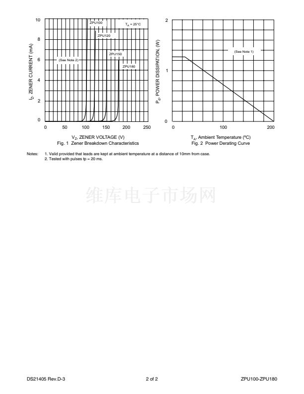
1. Valid provided that leads are kept at ambient temperature at a distance of 10mm from case.
2. Tested with pulses tp = 20 ms.
DS21405 Rev.D-3
1 of 2
ZPU100-ZPU180


 1
1
 2
2
