鈥?/div>
One 16-Bit Standard Timer and One 16-Bit Pulse
Width Modulator (PWM) Timer
Six Vectored Interrupts with Fixed Priority
Processor Speed Dividable by Firmware Control
Operating Current: 5 mA typical in USB Mode; 2.5 mA
typical in Serial Mode (@ 3 MHz); 5 mA typical in PS/2
Mode
16 Total Input/Output Pins (Open-Drain/Push-Pull)
Configurable
6 inputs with 3 level Programmable Reference
Comparators
16-Bit Programmable Watch-Dog Timer (WDT) with
Internal RC Oscillator
s
s
Identical Masked ROM Version (Z8C520)
On-Chip Oscillator that accepts a Ceramic Resonator or
External Clock
Hardware Support for PS/2, Serial, USB, and General-
Purpose I/O (GPIO)
Power Reduction Modes:
鈥?STOP Mode (functionality shut down except SMR)
鈥?HALT Mode (XTAL still running-peripherals active)
USB SIE Compliant with USB Spec 1.0
4.0 VDC to 6.0 VDC Operating Range @ 0
擄
C to +70
擄
C
s
s
s
s
s
s
s
GENERAL DESCRIPTION
Zilog鈥檚 Z8E520 (OTP) and Z8C520 (Masked ROM) micro-
controllers are low-power Z8
Plus
MCUs, designed for the
cost-effective implementation of USB and multiprotocol
pointing devices.
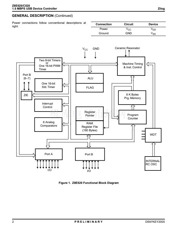
For applications demanding powerful I/O capabilities, the
Z8E520's input and output lines are grouped into two ports,
and are configurable under software control to provide tim-
ing, status signals, or parallel I/O.
Both 8-bit and 16-bit timers, with a large number of user se-
lectable modes, off-load the system of administering real-
time tasks such as counting/timing and I/O data communi-
cations.
The microcontroller clock frequency is derived from the
system clock by a programmable divider under firmware
control.
The device is capable of functioning in four distinct, select-
able communications modes: PS/2, RS232, GPIO (Gener-
al-purpose I/O), and USB. The communications mode de-
termines the functionality of the two special serial
communications pins (PB6 and PB7). The device is placed
in the required mode when firmware sets the specified
mode bit in the communications control register. The firm-
ware interface is similar in all modes. The same buffer area
in RAM will accept the data to be transmitted. Up to 8 bytes
may be loaded, and the data will actually be transmitted as
soon as the appropriate command is issued (setting In
Packet Ready in USB mode, for example).
DS97KEY2005
PRELIMINARY
1


 1
1
 2
2
 3
3
 4
4
 5
5
 6
6
 7
7
 8
8
 9
9
 10
10
 11
11
 12
12
 13
13
 14
14
 15
15
 16
16
 17
17
 18
18
 19
19
 20
20
 21
21
 22
22
 23
23
 24
24
 25
25
 26
26
 27
27
 28
28
 29
29
 30
30
 31
31
 32
32
 33
33
 34
34
 35
35
 36
36
 37
37
 38
38
 39
39
 40
40
 41
41
 42
42
 43
43
