P R E L I M I N A R Y
Z86317
CMOS Z8
廬
8-B
IT
MCU
P
RELIMINAR Y
C
USTOMER
P
ROCUREMENT
S
PECIFICA TION
Z86317
CMOS Z8
廬
8-B
IT
M
ICROCONTROLLER
FEATURES
Part
ROM
Number (KB)
Z86317
2
RAM* Speed
(Bytes) (MHz)
124
4
I/O
13
Package
(18-Pin)
DIP, SOIC
s
P24-P27 Can be Configured as a Voltage Divider
During Input Mode
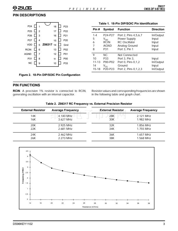
On-Chip Precision RC Oscillator (Tolerance =
鹵
10%)
Fast Instruction Pointer: 1.5
碌s
@ 4 MHz
ESD Protection Circuitry
Hardwired Watch-Dog Timer (WDT)
s
s
s
s
*General Purpose
s
s
s
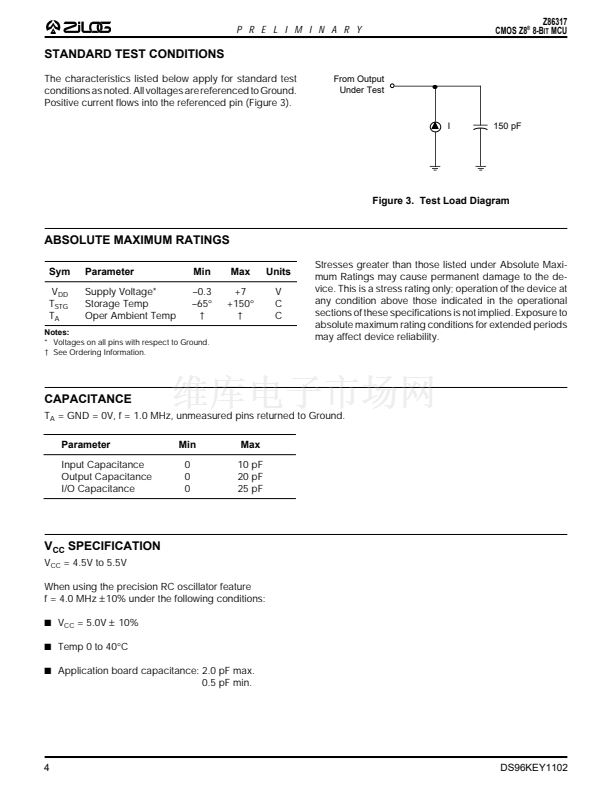
4.5- to 5.5-Volt Operating Range
0擄C to + 40擄C Operating Temperature Range
Low-Power Consumption: 33 mW (Typical)
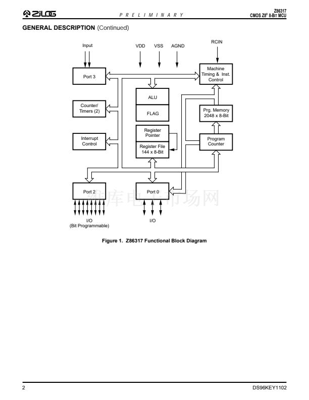
GENERAL DESCRIPTION
The Z86317 is a member of the Z8
廬
family of CMOS
microcontrollers architected to be used in mouse applica-
tions. These devices offer on-board pull-up and pull-down
resistors, a scalable trip-point buffer to accommodate
opto-transistor outputs, and high drive ports capable of up
to 10 mA current sinking per pin (six pins maximum).
A permanently enabled Watch-Dog Timer ensures opera-
tional reliability across a broad range of mouse application
environments. The precision RC oscillator filters out high-
frequency noise from the oscillator input pin. When config-
ured as inputs, P24-P27 are configured as voltage divider
(25K pull-up / 7.5K pull-down). The input levels are ad-
justed for connection to the emitters of the opto-transistors
and switch at a voltage level of 0.4 V
DD.
For applications requiring powerful I/O capabilities, the
Z86317 provides dedicated input and output lines that are
grouped into three ports. There are two basic address
spaces available to support this configuration: Program
Memory, and 124 bytes of general-purpose registers.
The Z86317 device provides two on-chip 8-bit program-
mable counter/timers with a large number of user-select-
able modes. Each counter/timer is driven by its own 6-bit
programmable prescaler. The Z86317 counter/timers
offload system real-time tasks such as counting/timing
and input/output data communications for increased sys-
tem efficiency.
Notes:
All Signals with a preceding front slash, "/", are active Low, e.g.; B//W
(WORD is active Low); /B/W (BYTE is active Low, only).
Power connections follow conventional descriptions below:
Connection
Power
Ground
Circuit
V
CC
GND
Device
V
DD
V
SS
DS96KEY1102
1


 1
1
 2
2
 3
3
 4
4
 5
5
 6
6
 7
7
 8
8
