WEDPZ512K72S-XBX
512K x 72 Synchronous Pipeline Burst ZBL SRAM
FEATURES
!
Fast clock speed: 150, 133, and 100MHz
!
!
*PRELIMINARY
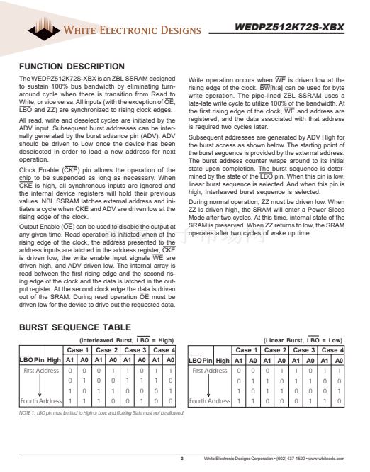
DESCRIPTION
The WEDC SyncBurst - SRAM employs high-speed, low-
power CMOS design that is fabricated using an advanced
CMOS process. WEDC鈥檚 32Mb SyncBurst SRAMs integrate
two 512K x 36 SSRAMs into a single BGA package to pro-
vide 512K x 72 configuration. All synchronous inputs pass
through registers controlled by a positive-edge-triggered
single-clock input (CLK). The ZBL or Zero Bus Latency
Memory utilizes all the bandwidth in any combination of
operating cycles. Address, data inputs, and all control sig-
nals except output enable and linear burst order are syn-
chronized to input clock. Burst order control must be tied
鈥淗igh or Low.鈥?Asynchronous inputs include the sleep
mode enable (ZZ). Output Enable controls the outputs at
any given time. Write cycles are internally self-timed and
initiated by the rising edge of the clock input. This feature
eliminates complex off-chip write pulse generation and pro-
vides increased timing flexibility for incoming signals.
*Preliminary product that is not fully characterized, non-qualified and is subject
to change without notice.
Fast access times: 3.8ns, 4.2ns, and 5.0ns
Fast OE access times: 3.8ns, 4.2ns, and 5.0ns
!
High performance 3-1-1-1 access rate
!
2.5V 鹵 5% power supply
!
Common data inputs and data outputs
!
Byte write enable and global write control
!
Six chip enables for depth expansion and address
pipeline
!
Internally self-timed write cycle
!
Burst control pin (interleaved or linear burst sequence)
!
Automatic power-down for portable applications
!
Commercial, industrial and military temperature ranges
!
Packaging:
鈥?52 PBGA package 17 x 23mm
F
UNCTIONAL
B
LOCK
D
IAGRAM
BENEFITS
512K x 36 SSRAM
!
30% space savings compared to equivalent TQFP
A
0-18
BWa
BWb
BWc
BWd
WE
0
OE
0
CLK
0
CKE
0
SA
BWa
BWb
BWc
BWd
WE
0
OE
0
CLK
CKE
CS1
CS2
CS2
ADV
LBO
ZZ
DQPA
DQA
0-7
DQPB
DQB
0-7
DQPC
DQC
0-7
DQPD
DQD
0-7
DQPA
DQA
0-7
DQPB
DQB
0-7
DQPC
DQC
0-7
DQPD
DQD
0-7
solution
!
Reduced part count
!
24% I/O reduction
!
Laminate interposer for optimum TCE match
!
Low Profile
!
Reduce layer count for board routing
!
Suitable for hi-reliability applications
!
User configurable as 1M x 36 or 2M x 18
!
Upgradable to 1M x 72 (contact factory for availability)
CS1
0
CS2
0
CS2
0
ADV
0
LBO
ZZ
512K x 36 SSRAM
SA
BWe
BWf
BWg
BWh
WE1
OE1
CLK1
CKE1
CS1
1
CS2
1
CS2
1
ADV1
BWa
BWb
BWc
BWd
WEO
OEO
CLK
CKE
CS1
CS2
CS2
ADV
LBO
ZZ
DQPA
DQA
0-7
DQPB
DQB
0-7
DQPC
DQC
0-7
DQPH
DQD
0-7
DQPE
DQE
0-7
DQPF
DQF
0-7
DQPG
DQG
0-7
DQPH
DQH
0-7
November 2003 Rev. 6
1
White Electronic Designs Corporation 鈥?(602) 437-1520 鈥?www.whiteedc.com


 1
1
 2
2
 3
3
 4
4
 5
5
 6
6
 7
7
 8
8
 9
9
 10
10
 11
11
 12
12
 13
13
 14
14
