廬
VN771K
QUAD SMART POWER SOLID STATE RELAY
FOR COMPLETE H BRIDGE CONFIGURATIONS
TYPE
VN771K
R
DS(on)
95 m鈩?(*)
I
OUT
9A (**)
V
CC
36V
(*) Total resistance of one side in bridge configuration
(**) Typical current limitation value
SUITED AS LOW VOLTAGE BRIDGE
s
LINEAR CURRENT LIMITATION
s
VERY LOW STAND-BY POWER DISSIPATION
s
SHORT CIRCUIT PROTECTED
s
STATUS FLAG DIAGNOSTIC (OPEN DRAIN)
s
INTEGRATED CLAMPING CIRCUITS
s
UNDERVOLTAGE PROTECTION
s
s
ORDER CODES
PACKAGE
SO-28
TUBE
VN771K
T&R
VN771K13TR
ESD PROTECTION
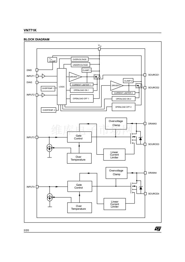
DESCRIPTION
The VN771K is a device formed by three
monolithic chips housed in a standard SO-28
package: a double high side and two low side
switches. Both the double high side and low side
switches are made using
|STMicroelectronics
VIPower鈩?M0-3 Technology. This device is
suitable to drive a DC motor in a bridge
configuration as well as to be used as a quad
switch for any low voltage application. The dual
high side switches have built-in thermal shutdown
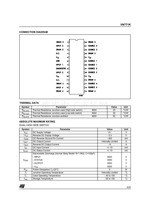
PIN FUNCTION
No
1, 3, 25, 28
2
4, 11
5, 10, 19, 24
6
7
8
9
12, 14, 15, 18
13
16, 17
20, 21
22, 23
26, 27
NAME
DRAIN 3
INPUT 3
N.C.
V
CC
GND
INPUT 1
DIAGNOSTIC
INPUT 2
DRAIN 4
INPUT 4
SOURCE 4
SOURCE 2
SOURCE 1
SOURCE 3
to protect the chips from overtemperature and
current limiter blocks to protect the device from
short circuit. Status output is provided to indicate
open load in off and on state and overtemperature.
The low side switches are two OMNIFET II types
(fully autoprotected Power MOSFET in VIPower鈩?/div>
technology). They have built-in thermal shutdown,
linear current limitation and overvoltage clamping.
Fault feedback for thermal intervention can be
detected by monitoring the voltage at the input pin.
FUNCTION
Drain of Switch 3 (low-side switch)
Input of Switch 3 (low-side switch)
Not Connected
Drain of Switches 1 and 2 (high-side switches) and Power Supply Voltage
Ground of Switches 1 and 2 (high-side switches)
Input of Switch 1 (high-side switches)
Diagnostic of Switches 1 and 2 (high-side switches)
Input of Switch 2 (high-side switch)
Drain of switch 4 (low-side switch)
Input of Switch 4 (low-side switch)
Source of Switch 4 (low-side switch)
Source of Switch 2 (high-side switch)
Source of Switch 1 (high-side switch)
Source of Switch 3 (low-side switch)
November 2002
1/20


 1
1
 2
2
 3
3
 4
4
 5
5
 6
6
 7
7
 8
8
 9
9
 10
10
 11
11
 12
12
 13
13
 14
14
 15
15
 16
16
 17
17
 18
18
 19
19
 20
20
