鈾?/div>
Glass passivated chip junction
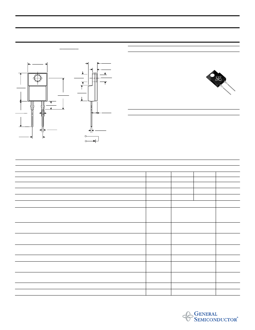
MECHANICAL DATA
Case:
ITO-220AC molded plastic body
Terminals:
Plated leads, solderable per MIL-STD-750,
Method 2026
Polarity:
As marked
Mounting Position:
Any
Weight:
0.08 ounce, 2.24 grams
Mounting Torque:
5 in. - lbs. max.
0.037 (0.94)
0.027 (0.69)
0.205 (5.20)
0.195 (4.95)
PIN 1
PIN 2
0.022 (0.55)
0.014 (0.36)
Dimensions in inches and (millimeters)
MAXIMUM RATINGS AND ELECTRICAL CHARACTERISTICS
Ratings at 25擄C ambient temperature unless otherwise specified.
SYMBOLS
UGF8FT
UGF8GT
UNITS
Maximum repetitive peak reverse voltage
Working peak reverse voltage
Maximum RMS voltage
Maximum DC blocking voltage
Maximum average forward rectified current at T
C
=100擄C
Peak forward surge current
8.3ms single half sine-wave superimposed
on rated load (JEDEC Method)
Maximum instantaneous forward voltage at I
F
= 8A
Maximum reverse leakage current
at working peak reverse voltage
Reverse recovery time at
I
F
=1.0A, di/dt=100A/碌s, V
R
=30V, I
rr
=0.1 I
RM
Maximum reverse recovery time at I
F
=0.5A, I
R
=1.0A, I
rr
=0.25A
Maximum reverse recovery current at
I
F
=10A, di/dt=50A/碌s,V
R
=30V
Maximum stored charge
I
F
=2A, di/dt=20A/碌s, V
R
=30V, I
rr
=0.1 I
RM
Typical thermal resistance from junction to case
Operating junction and storage temperature range
NOTE:
(1) Pulse test: 300碌s pulse width, 1% duty cycle
NOTICE:
Advanced product information is subject to change without notice
V
RRM
V
RWM
V
RMS
V
DC
I
(AV)
I
FSM
(NOTE 1)
300
225
210
300
8.0
100.0
1.30
1.00
10
350
50
35
5.5
55
5.0
400
300
280
400
Volts
Volts
Volts
Volts
Amps
Amps
T
J
=25擄C
T
J
=150擄C
T
J
=25擄C
T
J
=100擄C
Maximum
V
F
I
R
t
rr
t
rr
Volts
碌A
ns
ns
Amps
nC
擄C/W
擄C
T
C
=100擄C
I
RM
Q
rr
R
螛JC
T
J
, T
STG
-40 to+150
4/98


 1
1
 2
2
