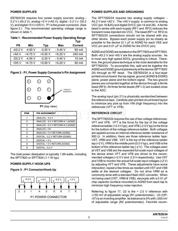
AN7820/24
EVALUATION BOARD
APPLICATION NOTE
FEATURES
鈥?20 and 40 MSPS Conversion Rate
鈥?On-Board Clock Drivers
鈥?Data Output and Strobe Signal
鈥?User Selectable Capture Clock
鈥?On-Board Reference Drivers
APPLICATIONS
鈥?Evaluation of SPT7820 and SPT7824
鈥?Engineering System Prototype Aid
鈥?Incoming Inspection Tool
鈥?Differential Linearity Error (DLE) Testing
鈥?Integral Linearity Error (ILE) Testing
鈥?AC Accuracy Testing: SNR, THD
鈥?Guide for System Layout
GENERAL DESCRIPTION
The EB7820/24 evaluation board demonstrates the perfor-
mance of the SPT7820 and SPT7824, monolithic high speed
analog-to-digital converters (ADCs). This document can
used as an application note and as supplemental information
to the existing data sheets (SPT7820 or SPT7824). Both the
SPT7820 and SPT7824 have analog input ranges of
鹵2
V.
The SPT7820 is capable of digitizing an analog input signal
into 10-bit words at a minimum update rate of 20 MSPS, while
the SPT7824 is capable of digitizing an analog input signal
into 10-bit words at a minimum update rate of 40 MSPS. Both
devices are pin-compatible. All input/output logic is TTL-
compatible.
Figure 1: EB7820/24 Block Diagram. (The full detail schematic is shown in figure 17.)
CLK
+
-
DGND
+5
TTL
COMP
CCLK
EB7820/24
REVB
-5.2
VFT
CLK
DGND
PART OF DB792
(DAUGHTER BOARD)
+2.5V
REF
SPT7820/24
LATCHES
-1
VFB
10
Dout
10
12-BIT DAC
(80 MSPS MAX)
VIN
VIN
10
DAC
OUT
AGND
-A5.2V
+A5
- D5.2V
+D5V
ADC OUT (TTL)
The EB7820/24 (鈮?4" X 7.5") consists of five separate sections:
- Reference circuits
- Clock circuits
- SPT7820 or SPT7824, 10-bit ADC (not included with the board)
- Output latches available through 26-pin female ribbon connector
- The DB792 DAC reconstruction board is a separate daughter board (鈮?2.5" X 3.0") that directly interfaces with the
EB7820/24


 1
1
 2
2
 3
3
 4
4
 5
5
 6
6
 7
7
 8
8
 9
9
 10
10
 11
11
 12
12
 13
13
 14
14
 15
15
 16
16
 17
17
