TMS370Cx0x
8-BIT MICROCONTROLLER
SPNS029C 鈥?SEPTEMBER 1995 鈥?REVISED FEBRUARY 1997
D
D
D
D
D
D
CMOS/ EEPROM/ EPROM Technologies on
a Single Device
鈥?Mask-ROM Devices for High-Volume
Production
鈥?One-Time-Programmable (OTP) EPROM
Devices for Low Volume Production
鈥?Reprogrammable EPROM Devices for
Prototyping Purposes
Internal System Memory Configurations
鈥?On-Chip Program Memory Versions
鈥?ROM: 8K Bytes
鈥?EPROM: 8K Bytes
鈥?Data EEPROM: 256 Bytes
鈥?Static RAM: 256 Bytes Usable as
Registers
Flexible Operating Features
鈥?Low-Power Modes: STANDBY and HALT
鈥?Commercial, Industrial, and Automotive
Temperature Ranges
鈥?Clock Options
鈥?Divide-by-4 (0.5 to 5 MHz SYSCLK)
鈥?Divide-by-1 (2 to 5 MHz SYSCLK)
Phase-Locked Loop (PLL)
鈥?Supply Voltage (V
CC
) 5 V
鹵10%
16-Bit General-Purpose Timer
鈥?Software Configurable as
a 16-Bit Event Counter, or
a 16-Bit Pulse Accumulator, or
a 16-Bit Input Capture Functions, or
Two Compare Registers, or a
Self-Contained Pulse-Width-Modulation
(PWM) Function
鈥?Software Programmable Input Polarity
鈥?Eight-Bit Prescaler, Providing a 24-Bit
Real-Time Timer
On-Chip 24-Bit Watchdog Timer
鈥?EPROM / OTP Devices: Standard
Watchdog
鈥?Mask-ROM Devices: Hard Watchdog,
Simple Counter, or Standard Watchdog
Flexible Interrupt Handling
鈥?Two Software-Programmable Interrupt
Levels
鈥?Global- and Individual-Interrupt Masking
鈥?Programmable Rising or Falling Edge
Detect
鈥?Individual Interrupt Vectors
FZ AND FN PACKAGES
( TOP VIEW )
V CC
A7
D7
D6
D3
RESET
D4
4 3 2 1 28 27 26
XTAL2 / CLKIN
XTAL1
A6
A5
A4
A3
A2
5
6
7
8
9
10
11
25
24
23
22
21
20
19
12 13 14 15 16 1718
VSS
A1
A0
D5
INT1
INT2
INT3
SCITXD
SCICLK
SCIRXD
T1IC / CR
T1PWM
T1EVT
MC
D
D
D
D
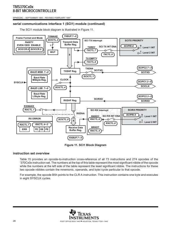
Serial Communications Interface 1 (SCI1)
鈥?Asynchronous Mode: 156K bps
Maximum at 5 MHz SYSCLK
鈥?Isosynchronous Mode: 25M bps
Maximum at 5 MHz SYSCLK
鈥?Full Duplex, Double-Buffered Receiver
(RX) and Transmitter (TX)
鈥?Two Multiprocessor Communication
Formats
TMS370 Series Compatibility
鈥?Register-to-Register Architecture
鈥?256 General-Purpose Registers
鈥?14 Powerful Addressing Modes
鈥?Instructions Upwardly Compatible With
All TMS370 Devices
CMOS/ TTL Compatible I / O Pins / Packages
鈥?All Peripheral Function Pins Software
Configurable for Digital I / O
鈥?21 Bidirectional Pins, 1 Input Pin
鈥?28-Pin Plastic and Ceramic Leaded Chip
Carrier Packages
Workstation / Personal Computed-Based
Development System
鈥?C Compiler and C Source Debugger
鈥?Real-time In-Circuit Emulation
鈥?Extensive Breakpoint / Trace Capability
鈥?Multi-Window User Interface
鈥?Microcontroller Programmer
Please be aware that an important notice concerning availability, standard warranty, and use in critical applications of
Texas Instruments semiconductor products and disclaimers thereto appears at the end of this data sheet.
Copyright
漏
1997, Texas Instruments Incorporated
PRODUCTION DATA information is current as of publication date.
Products conform to specifications per the terms of Texas Instruments
standard warranty. Production processing does not necessarily include
testing of all parameters.
POST OFFICE BOX 1443
鈥?/div>
HOUSTON, TEXAS 77251鈥?443
1


 1
1
 2
2
 3
3
 4
4
 5
5
 6
6
 7
7
 8
8
 9
9
 10
10
 11
11
 12
12
 13
13
 14
14
 15
15
 16
16
 17
17
 18
18
 19
19
 20
20
 21
21
 22
22
 23
23
 24
24
 25
25
 26
26
 27
27
 28
28
 29
29
 30
30
 31
31
 32
32
 33
33
 34
34
 35
35
 36
36
 37
37
 38
38
 39
39
 40
40
 41
41
 42
42
 43
43
 44
44
 45
45
 46
46
 47
47
 48
48
 49
49
