鈥?/div>
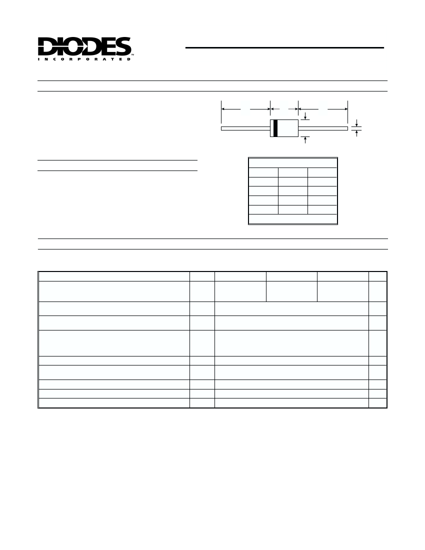
9.50
1.30
5.30
A
B
C
D
C
Mechanical Data
路
路
路
路
路
Case: DO-201AD, Molded Plastic
Leads: Solderable per MIL-STD-202,
Method 208
Polarity: Cathode band
Approx. Weight: 1.1 grams
Mounting Position: Any
All Dimensions in mm
Maximum Ratings and Electrical Characteristics
Single phase, half wave, 60Hz, resistive or inductive load.
For capacitive load, derate current by 20%.
Characteristic
Peak Repetitive Reverse Voltage
Working Peak Reverse Voltage
DC Blocking Voltage
Maximum Average Forward Current
(Note 2)
Maximum Peak One-Cycle
Surge Current
Forward Voltage (Note 1)
@ T
C
= 120擄C
@ 5碌s Sine Wave
@ 10ms Sine Wave
@ I
F
= 9.0A, T
J
= 25擄C
@ I
F
= 9.0A, T
J
= 125擄C
@ I
F
= 18A, T
J
= 25擄C
@ I
F
= 18A, T
J
= 125擄C
@T
J
= 25擄C
@ T
J
= 125擄C
Symbol
V
RRM
V
RWM
V
R
I
O
I
FSM
@ T
A
= 25擄C unless otherwise specified
SD930
30
SD940
40
9.0
2150
340
0.48
0.42
0.57
0.52
10,000
0.8
70
900
8.0
-65 to +150
SD945
45
Unit
V
A
A
V
FM
dv/dt
I
RM
C
j
R
qJL
T
j,
T
STG
V
V/碌s
mA
pF
K/W
擄C
Voltage Rate of Change
Peak Reverse Current
at Rated DC Blocking Voltage (Note 1)
Maximum Junction Capacitance (Note 2)
Typical Thermal Resistance Junction to Case (Note 4)
Operating and Storage Temperature Range
Notes:
1. Pulse width
攏
碌s - Duty Cycle
攏
2%.
2. Measured at 1.0MHz and applied reverse voltage of 4.0V.
3. Device mounted to heat sink with 1/8" lead length.
4. Thermal Resistance from Junction to Lead Vertical PC Board Mounting, 9.5mm Lead Length.
DS23026 Rev. C-2
1 of 3
SD930/SD940/SD945


 1
1
 2
2
 3
3
