Surface Mount
NE
W!
Voltage Variable Attenuator
10 to 2500 MHz
Features
RVA-2500
鈥?broadband, 10-2500 MHz
鈥?IP3, +43 dBm typ.
鈥?40 dB attenuation @ 1500 MHz
鈥?good VSWR at IN/OUT ports over attenuation range
鈥?minimal phase deviation over attenuation range
鈥?no external bias and RF matching network required
鈥?shielded case
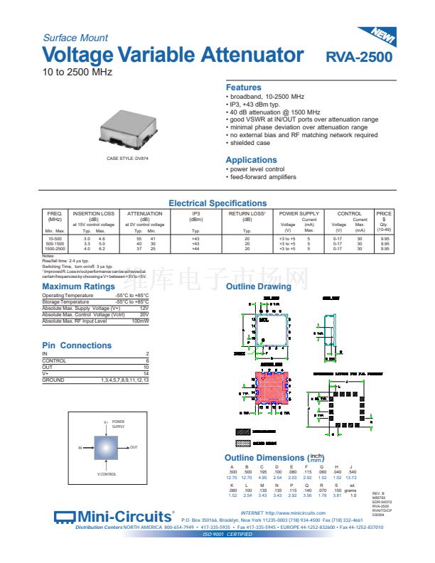
CASE STYLE: DV874
Applications
鈥?power level control
鈥?feed-forward amplifiers
Electrical Specifications
FREQ.
(MHz)
Min. Max.
10-500
500-1500
1500-2500
INSERTION LOSS
(dB)
at 15V control voltage
Typ. Max.
3.0
3.3
4.0
4.6
5.0
6.2
ATTENUATION
(dB)
at 0V control voltage
Typ. Min.
55
40
37
41
30
25
IP3
(dBm)
Typ.
+43
+43
+44
RETURN LOSS
1
(dB)
Typ.
20
20
20
POWER SUPPLY
Voltage
(V)
+3 to +5
+3 to +5
+3 to +5
Current
(mA)
Max.
5
5
5
CONTROL
Voltage
(V)
0-17
0-17
0-17
Current
Max.
(mA)
30
30
30
PRICE
$
Qty.
(10-49)
9.95
9.95
9.95
Notes:
Rise/fall time: 2.4
碌s
typ.
Switching Time, turn on/off: 3
碌s
typ.
1
Improved R. Loss in/out performance can be achieved at
certain frequencies by choosing a V+ between +3V to +5V.
Maximum Ratings
Operating Temperature
-55擄C to +85擄C
Storage Temperature
-55擄C to +85擄C
Absolute Max. Supply Voltage (V+)
12V
Absolute Max. Control Voltage (Vctrl)
20V
Absolute Max. RF Input Level
100mW
Outline Drawing
Pin Connections
IN
CONTROL
OUT
V+
GROUND
2
6
10
14
1,3,4,5,7,8,9,11,12,13
V+
POWER
SUPPLY
IN
OUT
Outline Dimensions (
inch
)
mm
V CONTROL
A
B
.500
.500
12.70 12.70
K
.060
1.52
L
.100
2.54
C
.195
4.95
M
.135
3.43
D
.100
2.54
N
.135
3.43
E
.080
2.03
P
.115
2.92
F
.115
2.92
Q
.140
3.56
G
.060
1.52
R
.070
1.78
H
J
.040
.540
1.02 13.72
S
wt.
.150 grams
3.81
1.0
Mini-Circuits
廬
INTERNET
http://www.minicircuits.com
P.O. Box 350166, Brooklyn, New York 11235-0003 (718) 934-4500 Fax (718) 332-4661
REV. B
M85783
EDR-5407/2
RVA-2500
RVN/TD/CP
030304
Distribution Centers
NORTH AMERICA 800-654-7949 鈥?417-335-5935 鈥?Fax 417-335-5945 鈥?EUROPE 44-1252-832600 鈥?Fax 44-1252-837010
ISO 9001 CERTIFIED


 1
1
