RECTRON
SEMICONDUCTOR
TECHNICAL SPECIFICATION
RS201L
THRU
RS207L
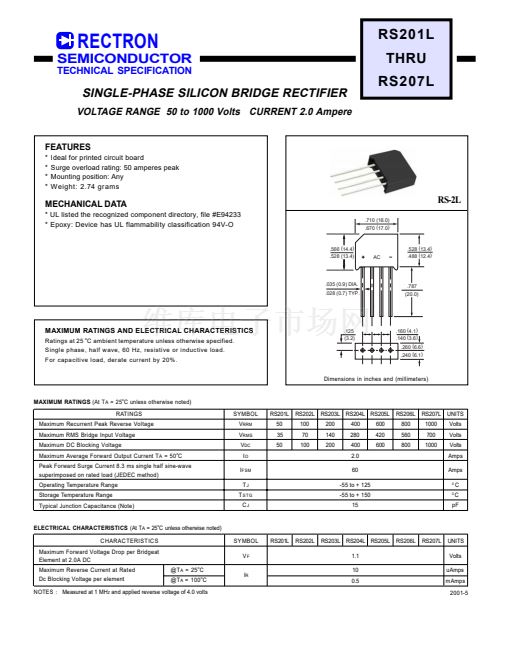
SINGLE-PHASE SILICON BRIDGE RECTIFIER
VOLTAGE RANGE 50 to 1000 Volts CURRENT 2.0 Ampere
FEATURES
*
*
*
*
Ideal for printed circuit board
Surge overload rating: 50 amperes peak
Mounting position: Any
Weight: 2.74 grams
MECHANICAL DATA
* UL listed the recognized component directory, file #E94233
* Epoxy: Device has UL flammability classification 94V-O
.710 (18.0)
.670 (17.0)
RS-2L
.566 (14.4)
.528 (13.4)
AC
.528 (13.4)
.488 (12.4)
.035 (0.9) DIA.
.028 (0.7) TYP.
.787
(20.0)
MAXIMUM RATINGS AND ELECTRICAL CHARACTERISTICS
Ratings at 25 C ambient temperature unless otherwise specified.
Single phase, half wave, 60 Hz, resistive or inductive load.
For capacitive load, derate current by 20%.
o
.125
(3.2)
.160 (4.1)
.140 (3.6)
.260 (6.6)
.240 (6.1)
Dimensions in inches and (millimeters)
MAXIMUM RATINGS
(At T
A
= 25
o
C unless otherwise noted)
RATINGS
Maximum Recurrent Peak Reverse Voltage
Maximum RMS Bridge Input Voltage
Maximum DC Blocking Voltage
Maximum Average Forward Output Current T
A
= 50 C
Peak Forward Surge Current 8.3 ms single half sine-wave
superimposed on rated load (JEDEC method)
Operating Temperature Range
Storage Temperature Range
Typical Junction Capacitance (Note)
o
SYMBOL
V
RRM
V
RMS
V
DC
I
O
I
FSM
T
J
T
STG
C
J
RS201L
50
35
50
RS202L
100
70
100
RS203L RS204L RS205L
200
140
200
400
280
400
2.0
60
-55 to + 125
-55 to + 150
15
600
420
600
RS206L
800
560
800
RS207L
1000
700
1000
UNITS
Volts
Volts
Volts
Amps
Amps
0
0
C
C
pF
ELECTRICAL CHARACTERISTICS
(At T
A
= 25 C unless otherwise noted)
CHARACTERISTICS
Maximum Forward Voltage Drop per Bridgeat
Element at 2.0A DC
Maximum Reverse Current at Rated
Dc Blocking Voltage per element
@T
A
= 25
o
C
@T
A
= 100 C
o
o
SYMBOL
V
F
I
R
RS201L
RS202L
RS203L RS204L RS205L
1.1
10
0.5
RS206L
RS207L
UNITS
Volts
uAmps
mAmps
2001-5
NOTES : Measured at 1 MH
Z
and applied reverse voltage of 4.0 volts


 1
1
 2
2
