鈮?/div>
1.2:1). The shunt
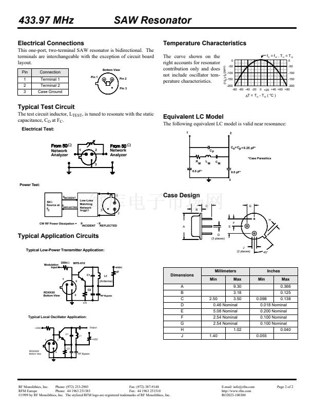
inductance, L
TEST
, is tuned for parallel resonance with C
O
at f
C
.
One or more of the following United States patents apply: 4,454,488 and
4,616,197.
Typically, equipment utilizing this device requires emissions testing and gov-
ernment approval, which is the responsibility of the equipment manufacturer.
Unless noted otherwise, case temperature T
C
= +25擄C鹵2擄C.
The design, manufacturing process, and specifications of this device are sub-
ject to change without notice.
7.
8.
Derived mathematically from one or more of the following directly measured
parameters: f
C
, IL, 3 dB bandwidth, f
C
versus T
C
, and C
O
.
Turnover temperature, T
O
, is the temperature of maximum (or turnover) fre-
quency, f
O
. The nominal frequency at any case temperature, T
C
, may be calcu-
lated from: f = f
O
[1 - FTC (T
O
-T
C
)
2
]. Typically,
oscillator
T
O
is 20擄C less than
the specified
resonator
T
O
.
This equivalent RLC model approximates resonator performance near the res-
onant frequency and is provided for reference only. The capacitance C
O
is the
static (nonmotional) capacitance between Pin1 and Pin 2 measured at low fre-
quency (10 MHz) with a capacitance meter. The measurement includes case
parasitic capacitance with a floating case. For usual grounded case applica-
tions (with grund connected to either Pin 1 or Pin 2 and to the case), add
approximately 0.25 pF to C
O
.
2.
3.
4.
5.
6.
9.
RF Monolithics, Inc.
Phone: (972) 233-2903
Fax: (972) 387-9148
RFM Europe
Phone: 44 1963 251383
Fax: 44 1963 251510
漏1999 by RF Monolithics, Inc. The stylized RFM logo are registered trademarks of RF Monolithics, Inc.
E-mail: info@rfm.com
http://www.rfm.com
RO2023-100300
Page 1 of 2


 1
1
 2
2
