鈮?/div>
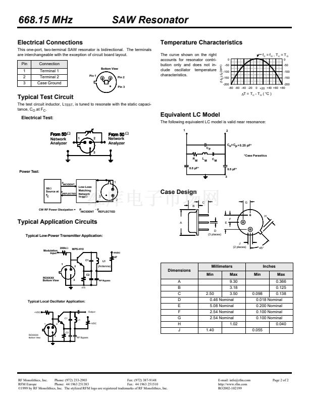
1.2:1). The shunt induc-
tance, L
TEST
, is tuned for parallel resonance with C
O
at f
C
. Typically, f
OSCILLA-
TOR
or f
TRANSMITTER
is less than the resonator f
C
.
One or more of the following United States patents apply: 4,454,488 and
4,616,197 and others pending.
Typically, equipment designs utilizing this device require emissions testing and
government approval, which is the responsibility of the equipment manufacturer.
Unless noted otherwise, case temperature T
C
= +25擄C鹵2擄C.
The design, manufacturing process, and specifications of this device are subject
to change without notice.
7.
8.
Derived mathematically from one or more of the following directly measured
parameters: f
C
, IL, 3 dB bandwidth, f
C
versus T
C
, and C
O
.
Turnover temperature, T
O
, is the temperature of maximum (or turnover) fre-
quency, f
O
. The nominal frequency at any case temperature, T
C
, may be calcu-
lated from: f = f
O
[1 - FTC (T
O
-T
C
)
2
]. Typically,
oscillator
T
O
is 20擄C less than
the specified
resonator
T
O
.
This equivalent RLC model approximates resonator performance near the reso-
nant frequency and is provided for reference only. The capacitance C
O
is the
static (nonmotional) capacitance between pin1 and pin 2 measured at low fre-
quency (10 MHz) with a capacitance meter. The measurement includes case
parasitic capacitance with a floating case. For usual grounded case applica-
tions (with ground connected to either pin 1 or pin 2 and to the case), add
approximately 0.25 pF to C
O
.
2.
9.
3.
4.
5.
6.
RF Monolithics, Inc.
Phone: (972) 233-2903
Fax: (972) 387-9148
RFM Europe
Phone: 44 1963 251383
Fax: 44 1963 251510
漏1999 by RF Monolithics, Inc. The stylized RFM logo are registered trademarks of RF Monolithics, Inc.
E-mail: info@rfm.com
http://www.rfm.com
RO2002-102199
Page 1 of 2


 1
1
 2
2
