RM10 - RM10Z
PRV : 200 - 800 Volts
Io : 1.2 - 1.5 Amperes
FEATURES :
*
*
*
*
*
High current capability
High surge current capability
High reliability
Low reverse current
Low forward voltage drop
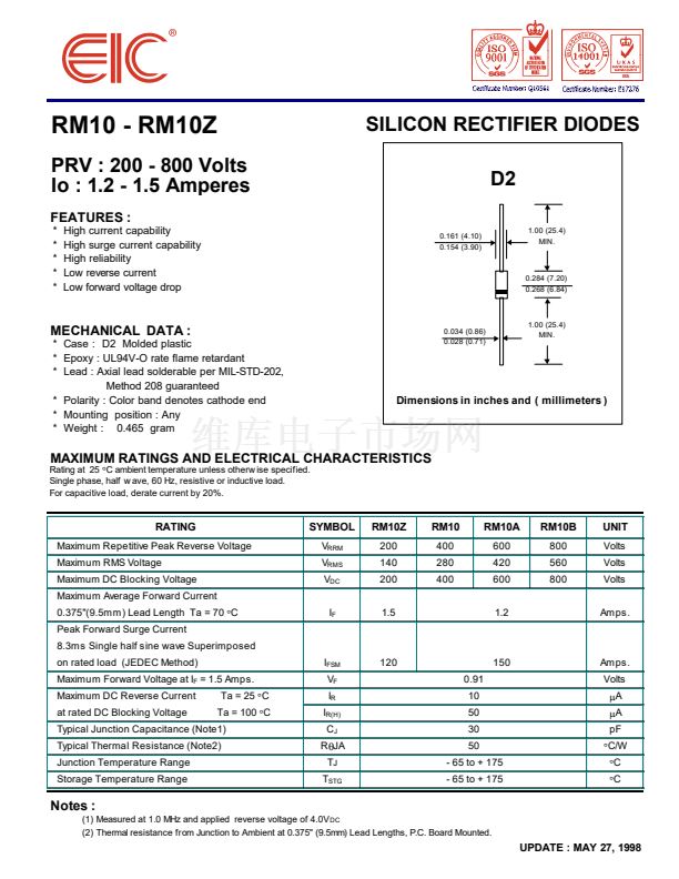
SILICON RECTIFIER DIODES
D2
0.161 (4.10)
0.154 (3.90)
1.00 (25.4)
MIN.
0.284 (7.20)
0.268 (6.84)
MECHANICAL DATA :
* Case : D2 Molded plastic
* Epoxy : UL94V-O rate flame retardant
* Lead : Axial lead solderable per MIL-STD-202,
Method 208 guaranteed
* Polarity : Color band denotes cathode end
* Mounting position : Any
* Weight : 0.465 gram
0.034 (0.86)
0.028 (0.71)
1.00 (25.4)
MIN.
Dimensions in inches and ( millimeters )
Rating at 25
擄
C ambient temperature unless otherw ise specified.
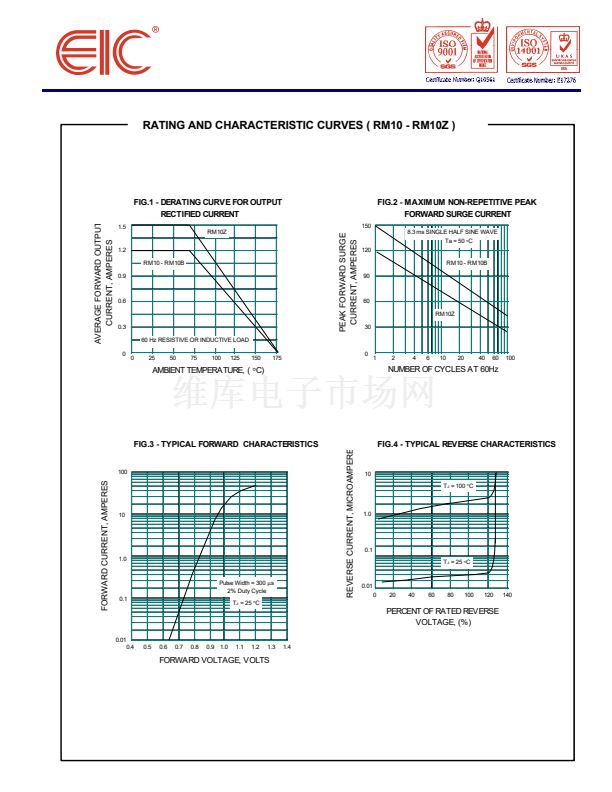
Single phase, half w ave, 60 Hz, resistive or inductive load.
For capacitive load, derate current by 20%.
MAXIMUM RATINGS AND ELECTRICAL CHARACTERISTICS
RATING
Maximum Repetitive Peak Reverse Voltage
Maximum RMS Voltage
Maximum DC Blocking Voltage
Maximum Average Forward Current
0.375"(9.5mm) Lead Length Ta = 70
擄
C
Peak Forward Surge Current
8.3ms Single half sine wave Superimposed
on rated load (JEDEC Method)
Maximum Forward Voltage at I
F
= 1.5 Amps.
Maximum DC Reverse Current
at rated DC Blocking Voltage
Ta = 25
擄
C
Ta = 100
擄
C
SYMBOL
V
RRM
V
RMS
V
DC
I
F
RM10Z
200
140
200
1.5
RM10
400
280
400
RM10A
600
420
600
1.2
RM10B
800
560
800
UNIT
Volts
Volts
Volts
Amps.
I
FSM
V
F
I
R
I
R(H)
C
J
R
胃
JA
T
J
T
STG
120
0.91
10
50
30
50
150
Amps.
Volts
碌
A
碌
A
pF
擄
C/W
擄
C
擄
C
Typical Junction Capacitance (Note1)
Typical Thermal Resistance (Note2)
Junction Temperature Range
Storage Temperature Range
- 65 to + 175
- 65 to + 175
Notes :
(1) Measured at 1.0 MHz and applied reverse voltage of 4.0V
DC
(2) Thermal resistance from Junction to Ambient at 0.375" (9.5mm) Lead Lengths, P.C. Board Mounted.
UPDATE : MAY 27, 1998


 1
1
 2
2
