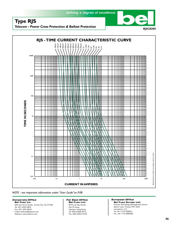
Type RJS
RJSD0303
Telecom - Power Cross Protection & Ballast Protection
m
Catalog
Number
Ampere
Rating
Voltage
Rating
Typical
Cold
Resistance
(ohm)
Volt-drop
@100%
In
(Vol)
max.
Melting
I
2
T< 10
mSec
(A
2
Sec)
Melting
I
2
T @10
In
(A
2
Sec)
Peak Surge Current
(Amp)
50 Pulses 1,000V
10 uS x 1000 u S
Maximum
Power
Dissipation
(W)
RJS 100
RJS 125
RJS 160
RJS
Fuses are primarily intended for use in telecommunication circuit
applications requiring low current protection with high surge tolerance.
They are typically used to replace heat coil type devices. They are designed
to be placed between the line input and the surge arresting components
(mov. gas tube, zenor diode, air gaps, etc.)
These fuses will withstand transient surge currents generated by
lightning in accordance with the attached table.
RJS
fuses guard protected circuitry against sustained overload or
short circuit conditions. Such sustained overloads may be generated by
accidental contact between utility cables and phone lines (power line
cross).
RJS
Fuse are used in circuits to obtain compliance with the test
requirements specified in UL 1950/60950 and Bellcor
e GR 1089.
100mA
125mA
160mA
200mA
250mA
300mA
350mA
400mA
500mA
600mA
700mA
750mA
1A
1.25 A
1.5 A
2A
2.5 A
3A
4A
5A
600V
600V
600V
600V
600V
600V
600V
600V
600V
600V
600V
600V
600V
600V
600V
600V
600V
600V
600V
600V
17
11
7
4.8
3.2
2.1
1.7
1.4
0.9
0.6
0.49
0.44
0.26
0.17
0.13
0.08
0.05
0.033
0.022
0.015
2.5
2.1
1.8
1.5
1.3
1.1
1.0
0.9
0.78
0.66
0.61
0.58
0.47
0.40
0.35
0.29
0.24
0.20
0.17
0.15
0.09
0.13
0.21
0.33
0.51
0.80
1.0
1.2
1.9
3.0
3.8
4.3
7.4
12
17
28
44
69
108
169
0.11
0.17
0.26
0.41
0.64
1.00
1.3
1.6
2.4
3.8
4.8
5.5
9.3
15
21
36
56
87
136
212
6
8
10
13
16
20
24
29
36
46
54
58
80
100
120
155
190
230
300
370
0.41
0.43
0.46
0.49
0.53
0.56
0.58
0.60
0.64
0.68
0.70
0.71
0.77
0.82
0.86
0.93
0.99
1.06
1.13
1.20
RJS 200
RJS 250
RJS 300
RJS 350
RJS 400
RJS 500
RJS 600
RJS 700
RJS 750
RJS 1
RJS 1.25
RJS 1.5
RJS 2
RJS 2.5
RJS 3
RJS 4
Electrical Characteristics
Testing Current
100%
135%
200%
500%
1000%
(UL/CSA STD. 248-14)
Blow Time
Minimum
Maximum
4 Hrs.
N/A
N/A
1 Hr
3 sec
20 sec
100 msec
1.5 sec
30 msec
300 msec
Approvals
Safety Agency
Approvals
Interrupting Rating
10,000A, AC@ 125V
200A, AC@ 250V
100A, AC@ 350V
60A, AC@ 600V
Power
Factor
0.7 - 0.8
0.7 - 0.8
Resistive
Resistive
rSc
Intended
Application
General Purpose
Primary Protection
Ballast Protection
Telecom Protection
RJS 5
Consult manufacturer for other ratings
Power Cross (Telecom) Rating
(Fuse Rated 0.1 - 1.5A)
Overload Current Voltage Clearing Time Limit
135% Fuse rating
200% Fuse Rating
2.2A
7A
40A
60A
600V
600V
600V
600V
600V
600V
Less
Less
Less
Less
Less
Less
than
than
than
than
than
than
1 hour
20 seconds
10 minutes
1 seconds
50 msec
20 msec
Double - exponential
Impulse Waveform
Current
r
S
Recognized File no.
E20624
Acceptance File no.
LR39772
Waveform Duration Of A/B Seconds
A=Rise Time=T1-T0
(1.25(b-a)
B=Duration=T2-T0
(Peak
Value) Ip
0.9 Ip
0.5 Ip
Operating Temperature
-55擄C to +125擄C
0.1 Ip
a
TO
b
T1
T2
Time
Environmental Specification
Soldering Techniques & Compatibility
Wave Solder: 260擄C, 10 sec max. (MIL-STD-202, Method 210)
Shock
MIL-STD-202, Method 213, Test Condition I
(100 G鈥檚 peak for 6 milliseconds)
Vibration
MIL-STD-202, Method 201 (10-55 Hz, 0.06 inch, total
excursion)
Salt Spray
MIL-STD-202, Method 101, Test condition B (48 hrs)
Insulation Resistance
MIL-STD-202, Method 302, Test Condition A
(After Opening) 10,000 ohms minimum
Solderability
MIL-STD-202, Method 208
Resistance to solder Heat
MIL-STD-202, Method 210, Test Condition C (260擄C, 20 sec)
Thermal Shock
MIL-STD-202, Method 107, Test Condition B (-65擄C to+125擄C)
Operating Temperature
-55擄C to +125擄C
Mechanical Dimensions
Standard Lead
A
B
C
D
0.76"+
/
-0.01"
(19.3+
/
-0.2mm)
0.80"+
/
-0.05
(20.3+
/
-1.27mm)
0.4" Typical
(10.0mm)
0.18" max
(4.6mm)
Short Lead
0.76"+
/
-0.01"
(19.3+
/
-0.2mm)
0.80"+
/
-0.05
(20.3+
/
-1.27mm)
0.11"+
/
-0.01"
(2.8+
/
-0.25mm)
0.18" max
(4.6mm)
Specifications subject to change without notice
C
A
D
RECOMMENDED
PCB HOLE SIZE AND SPACING
1.0mm DIA.
0.80鈥?( 20.3mm)
B
Physical Specification
Materials
Body: Glass;
Lead Wire: Tin-lead plated Copper, Diameter 0.032"
Marking
On fuse: 鈥渂el鈥? 鈥淭ype鈥濃€淐urrent Rating鈥?鈥淰oltage Rating鈥?鈥淎ppropriate
Safety Logos鈥?/div>
On label: Above info; Interrupting Rating plus 鈥渃鈥?/div>
Packaging
In bulk : 2,000 pcs per box. (standard Lead) 500 pcs per box. (short Lead)
ORDERING INFORMATION SEE PAGES 67 & 68
Bel Fuse Inc.
206 Van Vorst Street, Jersey City, NJ 07302 鈥?Tel: 201-432-0463 鈥?Fax: 201-432-9542 鈥?E-Mail: belfuse@belfuse.com
Website: www.belfuse.com
35


 1
1
 2
2
