RHRD660, RHRD660S
Data Sheet
January 2000
File Number
3746.3
6A, 600V Hyperfast Diodes
The RHRD660 and RHRD660S are hyperfast diodes with
soft recovery characteristics (t
rr
< 30ns). They have half the
recovery time of ultrafast diodes and are silicon nitride
passivated ion-implanted epitaxial planar construction.
These devices are intended for use as freewheeling/
clamping diodes and recti鏗乪rs in a variety of switching power
supplies and other power switching applications. Their low
stored charge and hyperfast soft recovery minimize ringing
and electrical noise in many power switching circuits
reducing power loss in the switching transistors.
Formerly developmental type TA49057.
Features
鈥?Hyperfast with Soft Recovery . . . . . . . . . . . . . . . . . . <30ns
鈥?Operating Temperature. . . . . . . . . . . . . . . . . . . . . . .175
o
C
鈥?Reverse Voltage Up To . . . . . . . . . . . . . . . . . . . . . . . .600V
鈥?Avalanche Energy Rated
鈥?Planar Construction
Applications
鈥?Switching Power Supplies
鈥?Power Switching Circuits
鈥?General Purpose
Ordering Information
PART NUMBER
RHRD660
RHRD660S
PACKAGE
TO-251
TO-252
RHR660
RHR660
BRAND
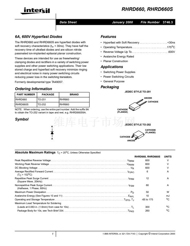
Packaging
JEDEC STYLE TO-251
ANODE
CATHODE
NOTE: When ordering, use the entire part number. Add the suf鏗亁 9A
to obtain the TO-252 variant in tape and reel, e.g. RHRD660S9A.
CATHODE
(FLANGE)
Symbol
K
JEDEC STYLE TO-252
CATHODE
(FLANGE)
A
CATHODE
ANODE
Absolute Maximum Ratings
T
C
= 25
o
C, Unless Otherwise Speci鏗乪d
UNITS
V
V
V
A
A
A
W
mJ
o
C
o
C
o
C
RHRD660, RHRD660S
Peak Repetitive Reverse Voltage . . . . . . . . . . . . . . . . . . . . . . . . . . . . . . . . . . . . . . . . . . . . . . . . . . . . . . . V
RRM
600
Working Peak Reverse Voltage . . . . . . . . . . . . . . . . . . . . . . . . . . . . . . . . . . . . . . . . . . . . . . . . . . . . . . . . V
RWM
DC Blocking Voltage . . . . . . . . . . . . . . . . . . . . . . . . . . . . . . . . . . . . . . . . . . . . . . . . . . . . . . . . . . . . . . . . . . . V
R
Average Recti鏗乪d Forward Current . . . . . . . . . . . . . . . . . . . . . . . . . . . . . . . . . . . . . . . . . . . . . . . . . . . . . I
F(AV)
(T
C
= 152
o
C)
Repetitive Peak Surge Current . . . . . . . . . . . . . . . . . . . . . . . . . . . . . . . . . . . . . . . . . . . . . . . . . . . . . . . . . I
FRM
(Square Wave, 20kHz)
Nonrepetitive Peak Surge Current . . . . . . . . . . . . . . . . . . . . . . . . . . . . . . . . . . . . . . . . . . . . . . . . . . . . . . . I
FSM
(Halfwave, 1 Phase, 60Hz)
Maximum Power Dissipation . . . . . . . . . . . . . . . . . . . . . . . . . . . . . . . . . . . . . . . . . . . . . . . . . . . . . . . . . . . . . P
D
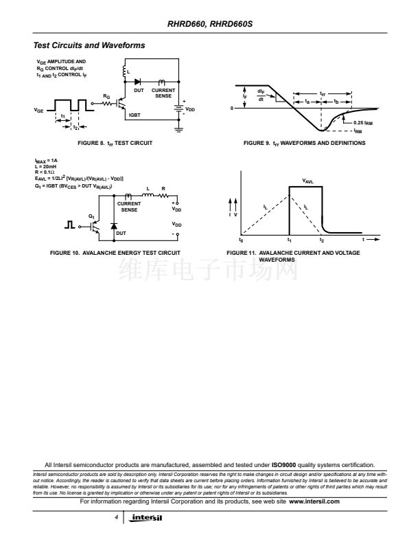
Avalanche Energy (See Figures 10 and 11) . . . . . . . . . . . . . . . . . . . . . . . . . . . . . . . . . . . . . . . . . . . . . . . E
AVL
Operating and Storage Temperature . . . . . . . . . . . . . . . . . . . . . . . . . . . . . . . . . . . . . . . . . . . . . . . . . . T
STG
, T
J
Maximum Lead Temperature for Soldering
(Leads at 0.063 in. (1.6mm) from case for 10s) . . . . . . . . . . . . . . . . . . . . . . . . . . . . . . . . . . . . . . . . . . . . . T
L
Package Body for 10s, see Tech Brief 334. . . . . . . . . . . . . . . . . . . . . . . . . . . . . . . . . . . . . . . . . . . . . . .T
PKG
600
600
6
12
60
50
10
-65 to 175
300
260
1
1-888-INTERSIL or 321-724-7143
|
Copyright
漏
Intersil Corporation 2000


 1
1
 2
2
 3
3
 4
4
