RGP02-12E // 20E
PRV : 1200 - 2000 Volts
Io : 0.5 Ampere
FEATURES :
*
*
*
*
*
*
*
Glass passivated junction
High current capability
High surge current capability
High reliability
Low reverse current
Low forward voltage drop
Fast switching for high efficiency
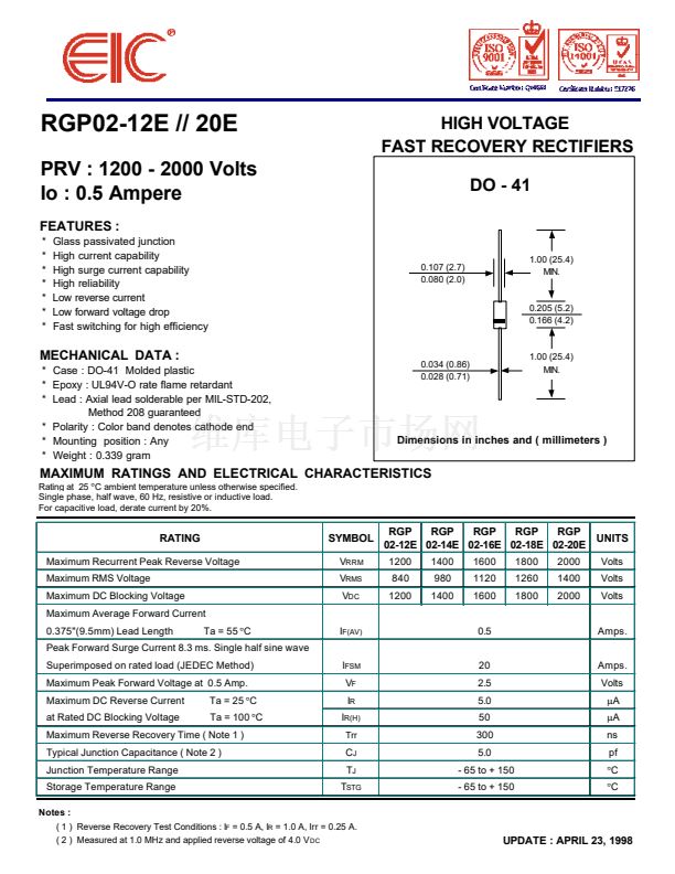
HIGH VOLTAGE
FAST RECOVERY RECTIFIERS
DO - 41
0.107 (2.7)
0.080 (2.0)
1.00 (25.4)
MIN.
0.205 (5.2)
0.166 (4.2)
MECHANICAL DATA :
* Case : DO-41 Molded plastic
* Epoxy : UL94V-O rate flame retardant
* Lead : Axial lead solderable per MIL-STD-202,
Method 208 guaranteed
* Polarity : Color band denotes cathode end
* Mounting position : Any
* Weight : 0.339 gram
Rating at 25
擄
C ambient temperature unless otherwise specified.
Single phase, half wave, 60 Hz, resistive or inductive load.
For capacitive load, derate current by 20%.
0.034 (0.86)
0.028 (0.71)
1.00 (25.4)
MIN.
Dimensions in inches and ( millimeters )
MAXIMUM RATINGS AND ELECTRICAL CHARACTERISTICS
RATING
Maximum Recurrent Peak Reverse Voltage
Maximum RMS Voltage
Maximum DC Blocking Voltage
Maximum Average Forward Current
0.375"(9.5mm) Lead Length
Ta = 55
擄C
SYMBOL
V
RRM
V
RMS
V
DC
RGP
RGP
RGP
RGP
RGP
UNITS
02-12E 02-14E 02-16E 02-18E 02-20E
1200
840
1200
1400
980
1400
1600
1120
1600
1800
1260
1800
2000
1400
2000
Volts
Volts
Volts
I
F(AV)
0.5
Amps.
Peak Forward Surge Current 8.3 ms. Single half sine wave
Superimposed on rated load (JEDEC Method)
Maximum Peak Forward Voltage at 0.5 Amp.
Maximum DC Reverse Current
at Rated DC Blocking Voltage
Ta = 25
擄C
Ta = 100
擄C
I
FSM
V
F
I
R
I
R(H)
Trr
20
2.5
5.0
50
300
5.0
- 65 to + 150
- 65 to + 150
Amps.
Volts
碌A(chǔ)
碌A(chǔ)
ns
pf
擄C
擄C
Maximum Reverse Recovery Time ( Note 1 )
Typical Junction Capacitance ( Note 2 )
Junction Temperature Range
Storage Temperature Range
Notes :
C
J
T
J
T
STG
( 1 ) Reverse Recovery Test Conditions : I
F
= 0.5 A, I
R
= 1.0 A, Irr = 0.25 A.
( 2 ) Measured at 1.0 MHz and applied reverse voltage of 4.0 V
DC
UPDATE : APRIL 23, 1998


 1
1
 2
2
