鈥?/div>
Ideal Front-End Filter for 291.4 MHz Wireless Receivers
Low-Loss, Coupled-Resonator Quartz Design
Simple External Impedance Matching
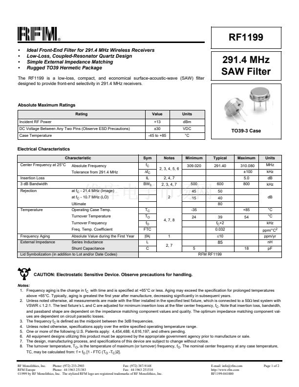
Rugged TO39 Hermetic Package
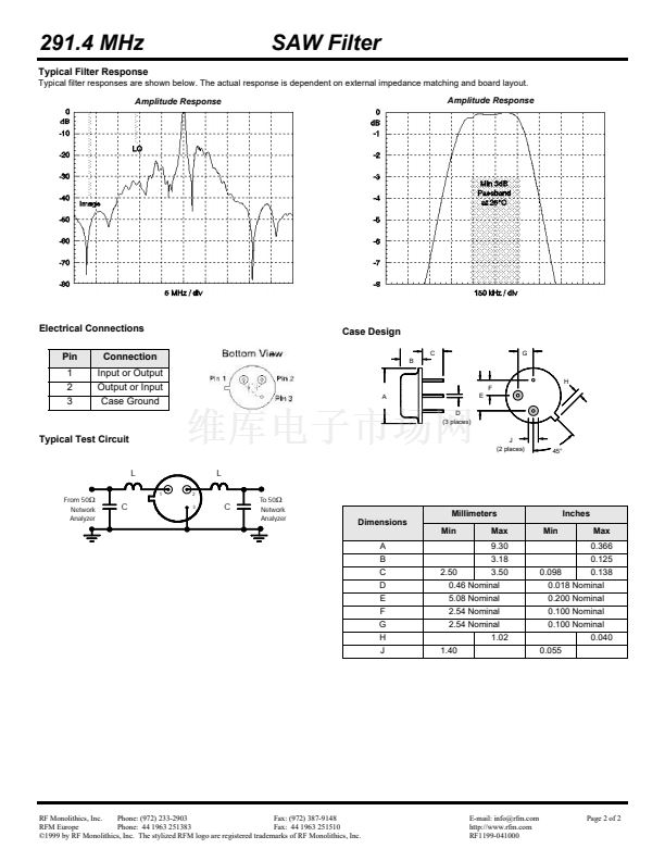
The RF1199 is a low-loss, compact, and economical surface-acoustic-wave (SAW) filter
designed to provide front-end selectivity in 291.4 MHz receivers.
291.4 MHz
SAW Filter
Absolute Maximum Ratings
Rating
Incident RF Power
DC Voltage Between Any Two Pins (Observe ESD Precautions)
Case Temperature
Value
+13
鹵30
-45 to +85
Units
dBm
VDC
擄C
TO39-3 Case
Electrical Characteristics
Characteristic
Center Frequency at 25擄C
Insertion Loss
3 dB Bandwidth
Rejection
at f
C
- 21.4 MHz (Image)
at f
C
- 10.7 MHz (LO)
Ultimate
Temperature
Operating Case Temp.
Turnover Temperature
Turnover Frequency
Freq. Temp. Coefficient
Frequency Aging
External Impedance
Absolute Value during the First Year
Series Inductance
Shunt Capacitance
Lid Symbolization (in addition to Lot and/or Date Codes)
T
C
T
O
f
O
FTC
|fA|
L
C
1
2, 7
5
RFM RF1199
4, 7, 8
-35
24
39
f
C
+2
0.032
鈮?0
2
Absolute Frequency
Tolerance from 291.4 MHz
Sym
f
C
鈭唂
C
IL
BW
3
Notes
2, 3, 4, 5, 6
2, 4, 7
2, 3, 4, 7
500
45
15
600
50
40
80
+85
54
擄C
擄C
kHz
ppm/擄C
2
ppm/yr
nH
18
pF
dB
Minimum
309.020
Typical
291.40
Maximum
310.080
鹵100
5.0
800
Units
MHz
kHz
dB
kHz
85
CAUTION: Electrostatic Sensitive Device. Observe precautions for handling.
Notes:
1. Frequency aging is the change in f
C
with time and is specified at +65擄C or less. Aging may exceed the specification for prolonged temperatures
above +65擄C. Typically, aging is greatest the first year after manufacture, decreasing significantly in subsequent years.
2. Unless noted otherwise, all measurements are made with the filter installed in the specified test fixture, which is connected to a 50鈩?test system with
VSWR
鈮?/div>
1.2:1. The test fixture鈥檚 L and C are adjusted for minimum insertion loss at the filter center frequency, f
C
. Note that insertion loss, bandwidth,
and passband shape are dependent on the impedance matching component values and quality. The optimum impedance matching component val-
ues are dependent on circuit parasitic losses.
3. The frequency f
C
is defined as the midpoint between the 3dB frequencies.
4. Unless noted otherwise, specifications apply over the entire specified operating temperature range.
5. One or more of the following U.S. Patents apply: 4,454,488; 4,616,197; and others pending.
6. All equipment designs utilizing this product must be approved by the appropriate government agency prior to manufacture or sale.
7. The design, manufacturing process, and specifications of this device are subject to change without notice.
8. The turnover temperature, T
O
, is the temperature of maximum (or turnover) frequency, f
O
. The nominal center frequency at any case temperature,
TC, may be calculated from: f = f
O
[1 - FTC (T
O
-T
C
)2].
RF Monolithics, Inc.
Phone: (972) 233-2903
Fax: (972) 387-9148
RFM Europe
Phone: 44 1963 251383
Fax: 44 1963 251510
漏1999 by RF Monolithics, Inc. The stylized RFM logo are registered trademarks of RF Monolithics, Inc.
E-mail: info@rfm.com
http://www.rfm.com
RF1199-041000
Page 1 of 2


 1
1
 2
2
