PHOTOMULTlPLlER TUBES
R636鈥?0, R758鈥?0
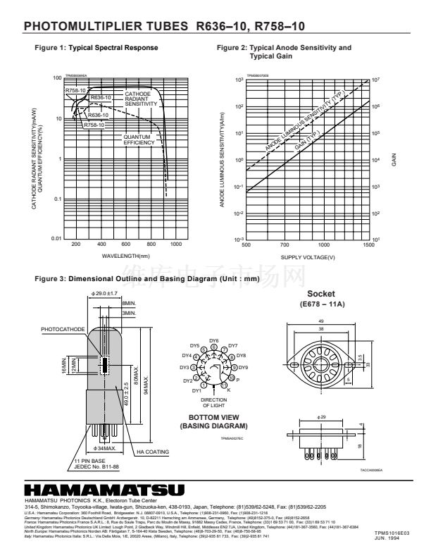
UV to Near IR (R636鈥?0:185 to 930 nm, R758鈥?0:160 to 930nm) Spectral Response
28mm(1-1/8 Inch) Diameter, GaAs(Cs) Photocathode, 9-stage,Side-On Type
GENERAL
Parameter
Spectral Response
Wavelength of Maximum Response
MateriaI
Photocathode
Minimum Effective Area
Window Material
Structure
Dynode
Number of Stages
Anode to Last Dynode
Direct Interelectrode
Capacitances
Anode to All Other Electrodes
Base
SuitabIe Socket
R636鈥?0
185 to 930
R758鈥?0
160 to 930
300 to 800
GaAs (Cs)
3 12
UV glass
Fused silica glass
Circular鈥揷age
9
4
6
JEDEC No.B11鈥?8
E678鈥?1A(option)
Unit
nm
nm
mm
pF
pF
MAXIMUM RATINGS (Absolute Maximum Values)
Supply Voltage
Average Anode Current
Parameter
Between Anode and Cathode
Between Anode and Last Dynode
Value
1500
250
0.001
Unit
Vdc
Vdc
mA
CHARACTERISTlCS (at 25
)
Min.
400
Typ.
550
62
63
48
0.53
4.5 10
5
250
2.8 10
4
2.8 10
4
2.2 10
4
0.1
2
20
Max.
Unit
A/lm
mA/W
Parameter
Luminous(2856K)
Cathode Sensitivity
at 350nm
at 632.8nm
Radiant
at 852.1nm
Red/White Ratio (with R鈥?8 filter)
Luminous(2856K)
Anode Sensitivity
Radiant
at 350nm
at 632.8nm
at 852.1nm
Gain
100
A/lm
A/W
2
nA
ns
ns
Anode Dark Current at 10A/lm
Anode Pulse Rise Time
Time Response
Electron Transit Time
After 30min. storage in darkness
NOTE:
Anode characteristics are measured with the voItage distribution ratio shown below.
VOLTAGE DlSTRlBUTlON RATlO AND SUPPLY VOLTAGE
K
Dy1
Dy2
Dy3
Dy4
Dy5
Dy6
Dy7
Dy8
Dy9
Electrodes
Ratio
1
1
1
1
1
1
1
1
1
1
SuppIy Voltage : 1250Vdc,
K : Cathode, Dy : Dynode,
P : Anode
P
Subject to local technical requirements and regulations, availability of products included in this promotional material may vary. Please consult with our sales office.
lnformation furnished by HAMAMATS U is believed to be reliabIe. However, no responsibility is assumed for possibIe inaccuracies or ommissions. Specifications are
subject to change without notice. No patent right are granted to any of the circuits described herein.
漏
1994 Hamamatsu Photonics K.K.


 1
1
 2
2
