鈥?/div>
Compliant with IrDA Speci鏗乧ation
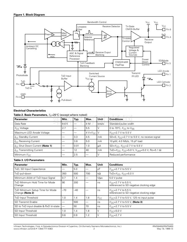
Data Rates 9.6 Kb/s to 4.0 Mb/s
Wide Range of Supply Voltage 2.7 to 5.5 V
Standby Current 3.3 mA at 5.0 V Typical
Shut Down Current 0.01
碌
A Typical
Excellent Power Supply Noise Rejection
Tri-State Receiver Output and TxD Disable
AC Coupled Transmit Input
鈥?Provides Integrated Protection for
Eye Safety
High DC Ambient Rejection
Independent LED Supply, Anode Pin Can Take
鈥?up to 9.0 V DC when not Transmitting and
鈥?up to 4.0 V above
V
CC
when Transmitting
Receiver Latency Less than 100
碌
s
Slimline Package:
H 4.0 mm x D 4.8 mm x L 9.8 mm
Absolute Maximum Ratings,
T
A
=25
擄
C (except where noted)
Supply Voltage Range, all states,
V
CC
.................................... 鈥?.5 to +7.0 V
LED Anode Voltage, not transmitting, V
LEDA
........................................9.0 V
LED Anode Voltage, transmitting, V
LEDA
.................................. 4.0 V +
V
CC
Input Currents, (pin 3 and 5) .............................................................. 20 mA
Output Sinking Current...................................................................... 50 mA
Storage Temperature,
T
S
.......................................................鈥?0 to +100擄C
Ambient Temperature, operating,
T
A
.......................................鈥?5 to +85擄C
Lead Solder Temperature, 230擄C ........................................................<10 s
IC Junction Temperature,
T
J
............................................................... 125擄C
Average IR LED Current, DC, I
LED
................................................... 100 mA
Repetitive Pulsed IR LED Current,
<90
碌
s,
t
on
<25%, I
LED(RP)
............................................................ 700 mA
Transmit Data Input Voltage, V
TxD
..................................鈥?.5 to
V
CC
+ 0.5 V
Receive Data Output Voltage, V
RxD .......................................
鈥?.5 to
V
CC
+ 0.5 V
Table 1. Pin Functions
Pin no.
1
2
3
4
Function
LED Anode
LED Cathode
TxD
RxD
Pin no.
5
6
7
8
Function
SD/Mode
V
CC
*Do not connect
GND
鈥?/div>
鈥?/div>
鈥?/div>
鈥?/div>
DESCRIPTION
With state of the art submicron BiCMOS circuitry,
coupled with In鏗乶eon optoelectronic expertise, the
IRMS6400/IRMT6400 outperforms its closest rival.
In鏗乶eon has incorporated a mode selection pin that
toggles the device to operate in FIR (4 Mb/s) or
SIR/MIR (9.6 Kb/s to 1.152 Mb/s) mode. Its exter-
nal Shut Down (SD) feature cuts current consump-
tion to typically 0.01 碌A(chǔ). The transmit input is AC
coupled, limiting transmit pulse duration to 70 碌s,
preventing transmitter damage and continuous
LED output. Mode select determines the data rate.
Low for 9.6 Kb/s to 1.152 Mb/s, high for 4 Mb/s.
*Pin 7 internally grounded
In鏗乶eon Technologies, Corp. 鈥?Optoelectronics Division 鈥?Cupertino, CA (formerly Siemens Microelectronics, Inc.)
www.in鏗乶eon.com/irdt 鈥?1-800-777-4363
1
May 18, 1999-13


 1
1
 2
2
 3
3
 4
4
 5
5
 6
6
 7
7
