ITALIANO
PSU 203
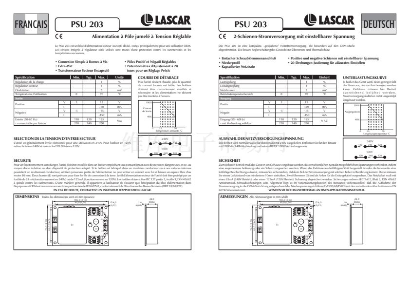
Alimentatore a polo doppio a tensione regolabile
Il PSU 203 貓 un alimentatore di rete compatto di tipo separato "aperto", studiato prevalentemente per le
applicazioni OEM. I circuiti integrati utilizzati per il regolatore lineare sono dotati di una protezione dai livelli
eccessivi di corrente e temperatura.
PSU 203
Adjustable Voltage Twin Rail Power Supply
The PSU 203 is a compact, split 'open' mains power supply unit designed primarily for OEM use. The linear
regulator Ics used feature over-current and over-temperature protection.
ENGLISH
鈥?Positive and Negative Adjustable Rails
鈥?20-Turn Trimmers for Accurate Setting
鈥?Semplice connessione con terminali a vite 鈥?Poli regolabili, positivo e negativo
鈥?Basso profilo
鈥?Trimmer a 20 giri per un'impostazione
鈥?Trasformatore di rete incapsulato
di precisione
Specifica
Regolazione carico
Regolazione linea
Ondulazione
Temperatura di esercizio
Uscita
Positiva
Negativa
Ingresso (50-60 Hz)
- selezionabile con collegamenti
V
I
V
I
鈥?Simple Screw-Terminal Connection
鈥?Low Profile
鈥?Encapsulated Mains Transformer
Specification
Load regulation
Line regulation
Ripple
Operating temperature
Output
Positive
Negative
Input (50-60Hz)
- link selectable
V
I
V
I
Min.
Typ.
Max.
1
1
5
70
15
150
-15
-150
125
250
Unit謾
%
%
mV
擄C
V
mA
V
mA
Vc.a.
0
5
-5
110
220
120
240
riscaldamento dell'alimentatore, tanto
minore sar脿 la corrente che pu貌 provenire
dallo stesso. Se necessario, le custodie
dovranno essere opportunamente ventilate
e gli alimentatori non dovranno essere
installati in posizione capovolta.
100%
Corrente
in uscita
40%
CURVA DI RIDUZIONE DELLE
PRESTAZIONI
Quanto maggiore 貓 il
Min.
Typ.
Max.
1
1
5
70
15
150
-15
-150
125
250
Unit
%
%
mV
擄C
V
mA
V
mA
VAC
DERATING CURVE
0
5
-5
110
220
120
240
The hotter the unit becomes the lower the
current that may be taken from it.
Enclosures should be adequately ventilated
if necessary and power supplies should not
be mounted upside down.
100%
Output
Current
40%
0
25
70
Ambient Temperature 擄C
SELEZIONE DELLA TENSIONE I/P DI RETE
0
25
70
Temperatura ambiente in 擄C
Solitamente l'alimentatore viene fornito collegato per il funzionamento a 240 V. Per il
funzionamento a 120 V rimuovere il collegamento a 240 V ed inserire ENTRAMBI i collegamenti a
120 V.
SELECTING MAINS I/P VOLTAGE
240V
120
240
120
240V
120
240
120
The unit is normally supplied connected for 240V operation. For 120V operation remove 240V
link and insert BOTH 120V links.
120V
120
240
120
120V
120
240
120
SICUREZZA
Per garantirne il funzionamento sicuro, l'alimentatore deve essere installato in una custodia che eviti il contatto accidentale con tensioni pericolose,
provvedendo ad isolarlo o a proteggerlo in modo opportuno. Qualora la custodia sia realizzata con un materiale conduttore o le superfici interne
siano provviste di un rivestimento conduttivo, assicurarsi che l'alimentatore non venga in alcun modo a contatto con essi e mantenere
un'intercapedine di almeno 10 mm. Sono previsti due terminali (E) come elementi di fissaggio per i conduttori di messa a terra. Il conduttore di rete in
ingresso all'alimentatore deve essere dotato di un fusibile da 63 mA (funzionamento a 240 V) o da 125 mA (funzionamento a 120 V). I fusibili devono
essere di tipo a spirale contro le sovratensioni transitorie, conformemente a IEC 127 Parte 2, Foglio 3, DIN 41662. In generale, spetta all'operatore
assicurarsi che l'integrazione dell'alimentatore nell'apparecchiatura OEM sia conforme alle relative sezioni della normativa EN 60742 in base alla
Direttiva Bassa Tensione (LVD 93/68/CEE).
IN CASO DI DUBBI, CONTATTARE UN TECNICO LASCAR.
For safe operation, the unit must be installed in an enclosure which prevents accidental contact with hazardous voltages, by providing appropriate
insulation or guarding. If the enclosure is made of a conducting material or the internal surfaces have a conductive coating, ensure that no part of
the power supply will come into contact with it, and maintain an air gap clearance of minimum 10mm. Two terminals (E) are provided as
anchorage for earth leads. The mains lead to the unit must be fused with a 63mA (240V operation)or a 125mA (120V operation) fuse. Fuses should
be IEC 127 part 2, sheet 3, DIN 41662 anti-surge spiral. In general, it is the responsibility of the user to ensure that the incorporation of the power
supply unit into the OEM equipment conforms to the relevant sections of EN 60742, in accordance with the Low Voltage Directive (LVD
IF IN DOUBT CONTACT AN APPLICATIONS ENGINEER.
93/68/EEC).
SAFETY
DIMENSIONS
All dimensions in mm (inches)
120 240 120
105.0 (4.13)
95.0 (3.74)
SET V-
IC2
R3
DIMENSIONI
Tutte le dimensioni sono espresse in mm (pollici)
105,0 (4,13)
95,0 (3,74)
120 240 120
鈭?/div>
4.0
(0.15)
1.6
(0.06)
22.0
(0.86)
SET V-
IC2
R3
鈭?/div>
4,0
(0,15)
1,6
(0,06)
22,0
(0,86)
76.0 (2.99)
66.0 (2.60)
CON2
L
N
CON1
E
E
R4
C4
R4
C4
76,0 (2,99)
66,0 (2,60)
CON2
L
N
CON1
E
E
V+ 0V
T1
0V
BR1
C2
C1
CON4
V-
C1
CON3
C3
IC1
R1
R2
CON3
C3
IC1
R1
R2
SET V+
SET V+
LASCAR ELECTRONICS LIMITED,
Specifications liable to change without prior warning
Sp茅cifications peuvent changer sans pr茅avis
Die technischen Daten k枚nnen ohne vorherige Ank眉ndigung ge盲ndert werden
Specifiche soggette a variazione senza preavviso
PSU 203
PSU 203
PSU 203
PSU 203
Issue 7
Edition 7
Ausgabe 7
Versione 7
April/2000
avril/2000
April/2000
Aprile/2000
M.C.
M.C.
M.C.
M.C.
Applies to PSU 203/4
Applique 脿 PSU 203/4
Gilt f眉r PSU 203/4
Applicabile a PSU 203/4
V+ 0V
T1
0V
BR1
C2
CON4
V-
MODULE HOUSE, WHITEPARISH,
SALISBURY, WILTSHIRE SP5 2SJ UK
TEL: +44 (0)1794 884567
FAX: +44 (0)1794 884616
E-MAIL: lascar@netcomuk.co.uk
PO BOX 50727, PALO ALTO, CA 94303-0727
TEL: +1 (650) 838 9027
FAX: +1 (650) 833 5432
E-MAIL: lascarus@pacbell.net
LASCAR ELECTRONICS, INC.
www.lascarelectronics.com


 1
1
 2
2
