Darlington Phototransistors
PNZ202S
(PN202S)
Darlington Phototransistor
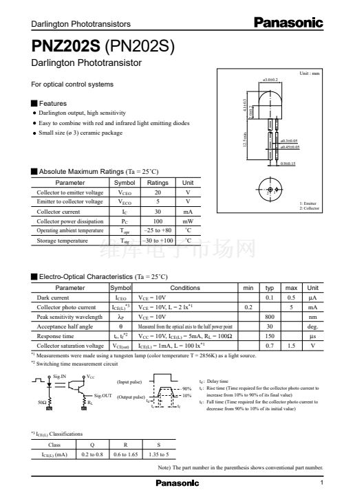
Unit : mm
For optical control systems
Features
Darlington output, high sensitivity
Easy to combine with red and infrared light emitting diodes
12.5 min.
4.1鹵0.3
2.0鹵0.2
酶3.0鹵0.2
Small size (酶 3) ceramic package
酶0.3鹵0.05
酶0.45鹵0.05
0.9鹵0.15
Absolute Maximum Ratings
(Ta = 25藲C)
Parameter
Collector to emitter voltage
Emitter to collector voltage
Collector current
Collector power dissipation
Operating ambient temperature
Storage temperature
Symbol
V
CEO
V
ECO
I
C
P
C
T
opr
T
stg
Ratings
20
5
30
100
鈥?5 to +80
鈥?0 to +100
Unit
V
V
mA
mW
藲C
藲C
2
1
1: Emitter
2: Collector
Electro-Optical Characteristics
(Ta = 25藲C)
Parameter
Dark current
Collector photo current
Peak sensitivity wavelength
Acceptance half angle
Response time
Collector saturation voltage
*1
*2
Symbol
I
CEO
I
CE(L)*3
位
P
胃
t
r
, t
f*2
V
CE(sat)
V
CE
= 10V
Conditions
V
CE
= 10V, L = 2 lx
*1
V
CE
= 10V
Measured from the optical axis to the half power point
V
CC
= 10V, I
CE(L)
= 5mA, R
L
= 100鈩?/div>
I
CE(L)
= 1mA, L = 100 lx
*1
min
0.2
typ
0.1
800
30
150
0.7
max
0.5
5
Unit
碌A(chǔ)
mA
nm
deg.
碌s
1.5
V
Measurements were made using a tungsten lamp (color temperature T = 2856K) as a light source.
Switching time measurement circuit
Sig.IN
V
CC
(Input pulse)
Sig.OUT
(Output pulse)
90%
10%
t
d
t
r
t
f
t
d
: Delay time
t
r
: Rise time (Time required for the collector photo current to
increase from 10% to 90% of its final value)
t
f
: Fall time (Time required for the collector photo current to
decrease from 90% to 10% of its initial value)
;;
*3
I
CE(L)
Classifications
Class
Q
0.2 to 0.8
R
0.6 to 1.65
S
1.35 to 5
Note) The part number in the parenthesis shows conventional part number.
I
CE(L)
(mA)
;;
next


 1
1
 2
2
 3
3
