21098765432121098765432109876543210987654321210987654321098765432109876543212109876543210987654321098765432121098765432109876543210987654321
1
2109876543212109876543210987654321098765432121098765432109876543210987654321210987654321098765432109876543212109876543210987654321098765432
21098765432121098765432109876543210987654321210987654321098765432109876543212109876543210987654321098765432121098765432109876543210987654321
21098765432121098765432109876543210987654321210987654321098765432109876543212109876543210987654321098765432121098765432109876543210987654321
21098765432121098765432109876543210987654321210987654321098765432109876543212109876543210987654321098765432121098765432109876543210987654321
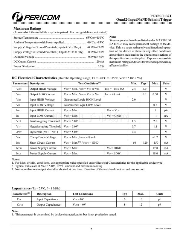
PI74FCT132T
Quad 2-Input NAND Schmitt Trigger
PI74FCT132T
Quad 2-Input NAND Schmitt Trigger
Product Features
Product Description
Pericom Semiconductor聮s PI74FCT series of logic circuits are
produced using the Company聮s advanced 0.8 micron CMOS
technology, achieving industry leading speed grades.
PI74FCT132 consists of four 2-input NAND gates that are able to
transform slowly changing input signals into highly defined,
jitter-free output signals.
Each gate contains a 2-input Schmitt trigger which uses positive
feedback to speed-up slow input transitions, and offer different
input threshold voltages for positive and negative-going transitions.
Resistor-ratios are used to determine this hysteresis between the
positive-going and negative-going input threshold.
聲 PI74FCT132T is pin compatible with bipolar FAST聶 Series at
a higher speed and lower power consumption
聲 TTL input and output levels
聲 Extremely low static power
聲 Hysteresis on all inputs
聲 Industrial operating temperature range: 聳40擄C to +85擄C
聲 Packages available:
聳 14-pin 150 mil wide plastic SOIC (W)
Logic Block Diagram
A
n
O
n
B
n
n: 0~3
Product Pin Description
Pin Name
A
0
-A
3
B
0
-B
3
O
0
-O
3
GND
V
CC
Description
Inputs
Inputs
Outputs
Ground
Power
4x
Product Pin Configuration
Truth Table
(1)
Inputs
A
n
L
B
n
L
H
L
H
Outputs
O
n
H
H
H
L
A
0
B
0
O
0
A
1
B
1
O
1
GND
1
2
3
4
5
6
7
14-PIN
W14
14
13
12
11
10
9
8
V
CC
A
2
B
2
O
2
A
3
B
3
O
3
L
H
H
Note:
1. H = HIGH Voltage Level
L = LOW Voltage Level
1
PS2003A 03/09/96


 1
1
 2
2
 3
3
