ADVANCE INFORMATION
21098765432121098765432109876543210987654321210987654321098765432109876543212109876543210987654321098765432121098765432109876543210987654321
21098765432121098765432109876543210987654321210987654321098765432109876543212109876543210987654321098765432121098765432109876543210987654321
PI6CV855-02
200 MHz SSTL_2 PLL Clock Driver
Product Features
聲 PLL clock distribution optimized for SSTL_2
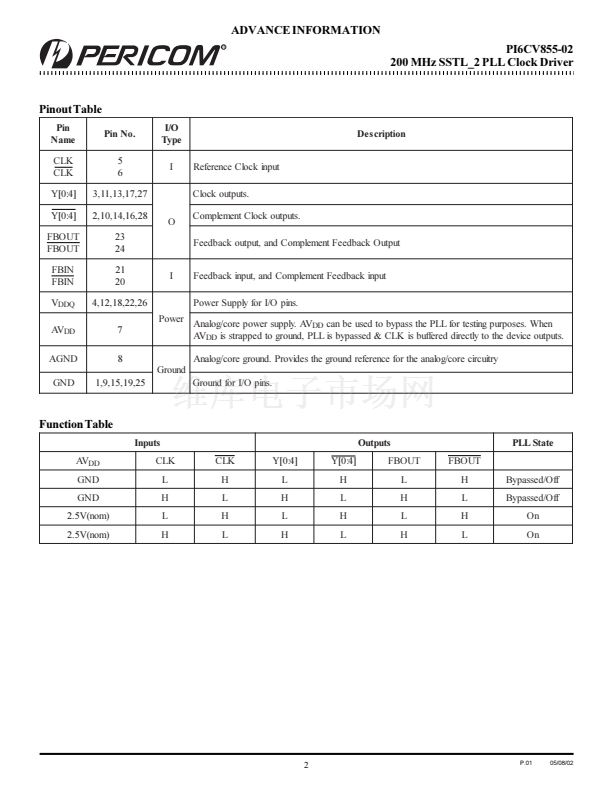
聲 Distributes one differential clock input pair to five differential
clock output pairs.
聲 Inputs (CLK,CLK) and (FBIN,FBIN): SSTL_2
聲 Outputs (Yx, Yx), (FBOUT, FBOUT): SSTL_2
聲 External feedback pins (FBIN,FBIN) are used to
synchronize the outputs to the input clocks.
聲 Operates at AV
DD
= 2.5V for core circuit and internal PLL,
and V
DDQ
= 2.5V for differential output drivers
聲 Packaging: Plastic 28-pin TSSOP (L28)
Product Description
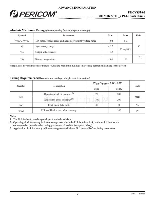
The PI6CV855-02 PLL Clock Buffer is designed for 2.5 V
DDQ
and 2.5V
AV
DD
operation and differential data input and output levels. The
device is a zero delay buffer that distributes a differential clock input
pair (CLK, CLK) to five differential pairs of clock outputs (Y[0:4],
Y[0:4]) and one differential pair feedback clock outputs (FBOUT,
FBOUT). The clock outputs are controlled by the input clocks (CLK,
CLK), the feedback clocks (FBIN,FBIN), and the Analog Power input
(AV
DD
). When the AV
DD
is strapped low, the PLL is turned off and
bypassed for test purposes.
The PI6CV855-02 is able to track Spread Spectrum Clocking to reduce
EMI.
Block Diagram
Pin Configuration
Y0
Y0
CLK
CLK
FBIN
FBIN
GND
Y0
Y0
VDDQ
CLK
CLK
AVDD
AGND
GND
Y1
Y1
VDDQ
Y2
Y2
1
2
3
4
5
6
7
8
9
10
11
12
13
14
28
27
26
25
24
Y4
Y4
VDDQ
GND
FBOUT
FBOUT
VDDQ
FBIN
FBIN
GND
VDDQ
Y3
Y3
GND
Y1
Y1
PLL
Y2
Y2
Y3
Y3
Y4
Y4
28-Pin
L
23
22
21
20
19
18
17
16
15
AV
DD
Logic
and
Test Ciruit
FBOUT
FBOUT
1
P.01
05/08/02


 1
1
 2
2
 3
3
 4
4
 5
5
 6
6
 7
7
 8
8
 9
9
