鈥?/div>
Description
The PI6C9910 is a low-skew clock driver designed to simplify
clock distribution in systems requiring near synchronous clocks. A
typical application is in SDRAM modules. Each of the eight
outputs (Q0-Q7) can drive individual 50鈩?transmission lines with
minimal distortion or skew, and full 5V swing.
An on-chip phase-locked loop (PLL) synchronizes the feedback
(FB) to the reference (REF) input, achieving 鈥渮ero-delay鈥?buffered
outputs.
Inserting an external counter between any of the Qx outputs and the
FB pin allows for generation of eight synchronous clock copies
whose frequency is a multiple of a lower frequency REF input.
The voltage-controlled oscillator (VCO) frequency is determined
by the filtered ouput coming from the Phase/Frequency Detector.
The frequency select (FS) input sets the VCO operating range.
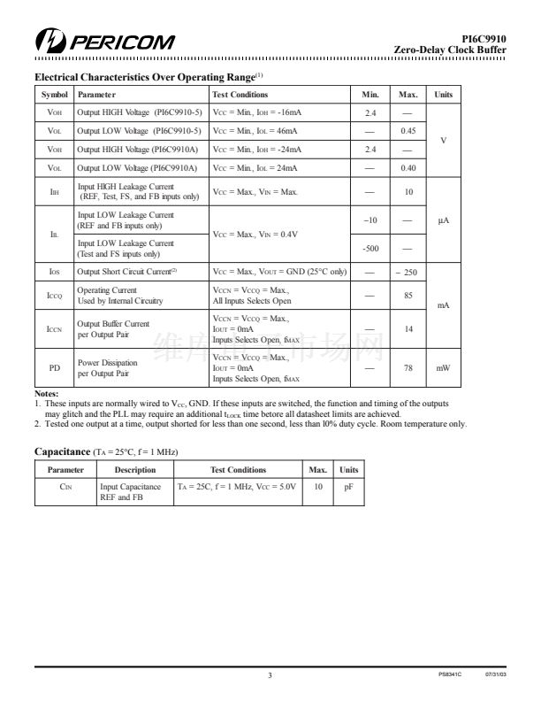
PI6C9910-5 has unbalanced output drivers (TTL), and is fully
compatible with the Cypress CY7B9910-5. The PI6C9910A features
balanced-drive outputs (CMOS) for improved rise/fall time
symmetry.
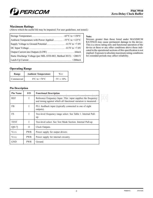
The FS and TEST inputs have internal pull-up resistors.
Test Mode
In normal operation the TEST pin is tied to ground. For testing
purposes it can have a removable jumper to ground or a 100鈩?/div>
pull-down resistor. When the TEST pin is driven HIGH, the VCO
output is disconnected, and all eight outputs (Q0-Q7) are directly
driven from the REF input.
Block Diagram
TEST
Phase
Freq.
Det
Pinout
FB
REF
FS
Filter
Voltage
Controlled
Oscillator
Q0
Q1
Q2
Q3
Q4
Q5
Q6
Q7
REF
V
CCQ
FS
NC
V
CCQ
V
CCN
Q
0
Q1
GND
Q2
Q3
V
CCN
1
2
3
4
5
6
7
8
9
10
11
12
24
23
22
21
20
19
18
17
16
15
14
13
GND
TEST
NC
GND
V
CCN
Q7
Q6
GND
Q5
Q4
V
CCN
FB
1
PS8341C
07/31/03


 1
1
 2
2
 3
3
 4
4
 5
5
 6
6
