PI5C16210
21098765432121098765432109876543210987654321210987654321098765432109876543212109876543210987654321098765432121098765432109876543210987654321
21098765432121098765432109876543210987654321210987654321098765432109876543212109876543210987654321098765432121098765432109876543210987654321
20-Bit, 2-Port Bus Switch
Product Features:
Near-zero propagation delay
5
Ohm
switches connect inputs to outputs
Direct bus connection when switches are ON
32X384 function with flow through pinout make board
layout easier
鈥?Ultra-low quiescent power (0.5碌W typical)
鈥?ideally suited for notebook applications
鈥?Industrial operating temperature: 鈥?0擄C to +85擄C
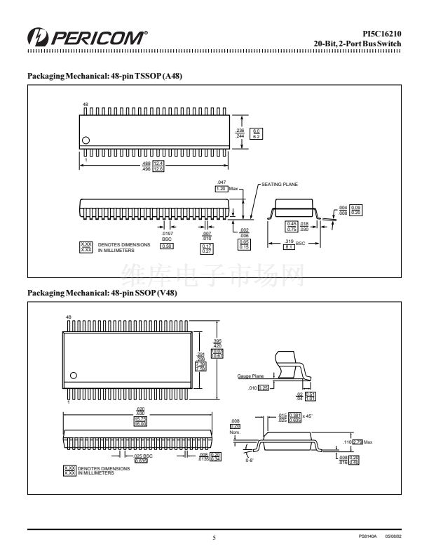
鈥?Packages available:
鈥?48-pin 150-mil wide plastic BQSOP (B)
鈥?48-pin 173-mil wide plastic TVSOP (K)
鈥?48-pin 240-mil wide plastic TSSOP (A)
鈥?48-pin 300-mil wide plastic SSOP (V)
鈥?/div>
鈥?/div>
鈥?/div>
鈥?/div>
Product Description:
Pericom Semiconductor鈥檚 PI5C series of BusSwitch circuits are
produced in the Company鈥檚 advanced sub-micron CMOS
technology, achieving industry leading speed.
The PI5C16210 is configured as 20-bit, 2-port bus switches
designed with a low ON resistance (5
Ohm)
allowing inputs to be
connected directly to outputs. The bus switch creates no additional
propagational delay or additional ground bounce noise. The
switches are turned ON by the Bus Enable (xOE) input signal.
Product Pin Configuration
NC
1A
1
1A
2
1A
3
1A
4
1A
5
1A
6
GND
1A
7
1A
8
1A
9
1A
10
2A
1
2A
2
V
CC
2A
3
GND
2A
4
2A
5
2A
6
2A
7
2A
8
2A
9
2A
10
1
2
3
4
5
6
7
8
9
10
11
12
13
14
15
16
17
18
19
20
21
22
23
24
48
47
46
45
44
43
42
41
40
39
38
37
36
35
34
33
32
31
30
29
28
27
26
25
1OE
2OE
1B
1
1B
2
1B
3
1B
4
1B
5
GND
1B
6
1B
7
1B
8
1B
9
1B
10
2B
1
2B
2
2B
3
GND
2B
4
2B
5
2B
6
2B
7
2B
8
2B
9
2B
10
Logic Block Diagram
1A
1
1B
1
1A
10
1B
10
1OE
2A
1
2B
1
48-Pin
A48
B48
K48
V48
2A
10
2B
10
2OE
Truth Table
(1)
Inputs
1O E
L
L
H
H
2O E
L
H
L
H
Inputs /Outputs
1A,1B
1A = 1B
1A = 1B
Z
Z
2A,2B
2A = 2B
Z
2A = 2B
Z
Product Pin Description
Pin Name
1OE, 2OE
1A1-1A10, 2A1-2A10
1B1 - 1B10, 2B1 - 2B10
Description
Bus Enable Inputs (Active LOW)
Bus A
Bus B
Note:
1. H = High Voltage Level
L = Low Voltage Level
Hi-Z = High Impedance
1
PS8140A
05/08/02


 1
1
 2
2
 3
3
 4
4
 5
5
 6
6
