Units to 500 MHz / Continuous 0擄 to 180擄 Adjustment / Voltage Controlled / Low Insertion Loss
180擄 min. @ f
1.75 dB max.
鈩?/div>
nom.
1.6:1 max.
0 dBm max.*
0.5 to +15 V typ.
0.5 to +30 V max.
1% of f
o
max.
For complete Model Number replace *** with desired Center Frequency, f
o
in MHz.
General Notes:
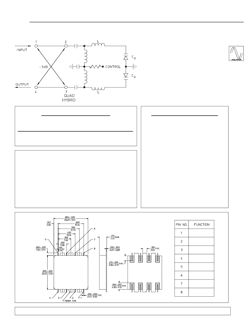
1. The PEG-3E series of voltage controlled phase shifters uses a lumped
element design for high performance in a space saving surface mount
package.
2. Phase control is achieved by the application of a 0 - 15 Volt control signal
which can be modulated at rates up to 1% of the RF center frequency. This
signal varies the capacitance of two varactor diodes that form part of a tuned
LC circuit connected across the output ports of a 90擄 quadrature hybrid.
The change in the reactance causes a shift in the phase of an RF signal
passed through the hybrid.
3. These Phase Shifters are designed for high reliability and can be supplied
screened to meet military and space applications.
Modulation Rate:
General Characteristics
Phase Stability:
0.1擄/ 擄C
Weight, nominal:
0.32 oz. (9 g)
Operating Temp:
-- 20擄 to +85擄C
*Unit may be operated at +10 dBm in reduced
control range of 1.5 - 15 V. (+30V no damage.)
E-Package Outline
NOTES:
1. Tolerance on 3 place decimals
鹵
.010(.25) except as noted.
2. Dimensions in inches over millimeters.
3. All unmarked pins are case ground.
4. Pins 1 & 8 connected internally.
Control
Ground
Ground
RF
RF
Ground
Ground
Control
29Apr96
F rf t e if r to c n a t
M ERRI AC /41 Faifel Pl,W estCal el,NJ,07006 / 973-
o ur h r n o ma in o t c
M
ri d .
dw l
575-
1300 /FAX 973- 0531
575-


 1
1
