鈥?/div>
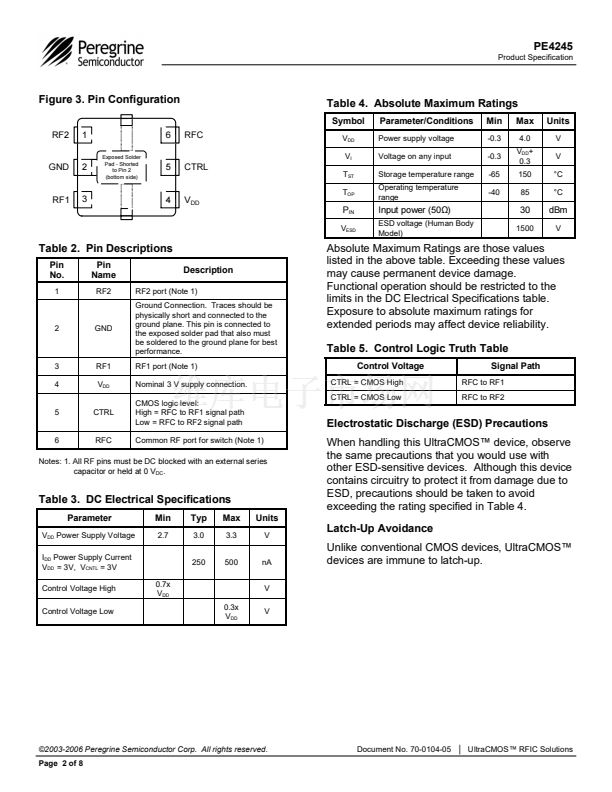
Available in a 6-lead DFN package
Figure 2. Package Type
6-lead DFN
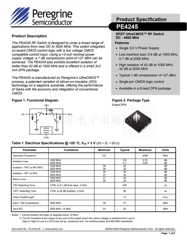
RF1
RF2
CMOS
Control
Driver
CTRL
Table 1. Electrical Specifications @ +25 擄C, V
DD
= 3 V
(ZS = ZL = 50
鈩?
Parameter
Operation Frequency
1
Insertion Loss
Isolation 鈥?RFC to RF1/RF2
Isolation 鈥?RF1 to RF2
Return Loss
鈥極N鈥?Switching Time
鈥極FF鈥?Switching Time
Video Feedthrough
2
Input 1 dB Compression
Input IP3
2000 MHz
2000 MHz, 14 dBm
26
43
1000 MHz
2000 MHz
1000 MHz
2000 MHz
1000 MHz
2000 MHz
1000 MHz
2000 MHz
CTRL to 0.1 dB final value, 2 GHz
CTRL to 25 dB isolation, 2 GHz
Conditions
Minimum
DC
Typical
Maximum
4000
Units
MHz
dB
dB
dB
dB
dB
dB
dB
dB
ns
ns
mV
pp
dBm
dBm
39
30
34
27
21
20
0.6
0.7
42
32
36
29
23
22
200
90
15
27
45
0.75
0.85
Notes: 1. Device linearity will begin to degrade below 10 MHz.
2. The DC transient at the output of any port of the switch when the control voltage is switched from Low to
High or High to Low in a 50
鈩?/div>
test set-up, measured with 1ns risetime pulses and 500 MHz bandwidth.
Document No. 70-0104-05
鈹?/div>
www.psemi.com
漏2003-2006 Peregrine Semiconductor Corp. All rights reserved.
Page 1 of 8


 1
1
 2
2
 3
3
 4
4
 5
5
 6
6
 7
7
 8
8
