NTE999M
Integrared Circuit
Programmable Precision Reference
Description:
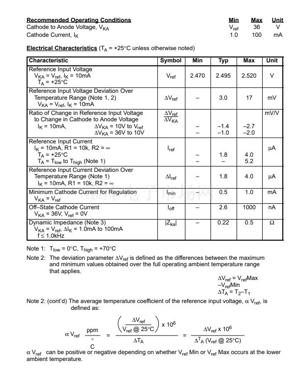
The NTE999M integrated circuit is a three鈥搕erminal programmable shunt regulator. This monolithic
IC voltage reference operates as a low temperature coefficient zener which is programmable from
V
ref
to 36 volts with two external resistors. This device exhibits a wide operating current range of 1.0
to 100mA with a typical dynamic impedance of 0.22鈩? The characteristics of this reference make it
an excellent replacement for zener diodes in many applications such as digital voltmeters, power sup-
plies, and op amp circuitry. The 2.5 volt reference makes it convenient to obtain a stable reference
from 5.0 volt logic supplies, and since the NTE999M operates as a shunt regulator, it can be used as
either a positive or negative voltage reference.
Features:
D
Programmable Output Voltage to 36 Volts
D
Voltage Reference Tolerance:
鹵1.0%
D
Low Dynamic Output Impedance: 0.22鈩?Typical
D
Sink Current Capability of 1.0 to 100mA
D
Equivalent Full Range Temperature Coefficient of 50ppm/擄C Typical
D
Temperature Compensated for Operation over Full Rated Operating Temperature Range
D
Low Output Noise Voltage.
Absolute Maximum Ratings:
(T
A
= 0擄 to +70擄C, unless otherwise noted.)
Cathode to Anode Voltage, V
KA
. . . . . . . . . . . . . . . . . . . . . . . . . . . . . . . . . . . . . . . . . . . . . . . . . . . . . . 37V
Cathode Current Range, Continuous, I
K
. . . . . . . . . . . . . . . . . . . . . . . . . . . . . . . . . . . . 鈥?00 to +150mA
Reference Input Current Range, Continuous, I
ref
. . . . . . . . . . . . . . . . . . . . . . . . . . . . 鈥?.05 to +10mA
Total Power Dissipation (T
A
= +25擄C), P
D
. . . . . . . . . . . . . . . . . . . . . . . . . . . . . . . . . . . . . . . . . . 725mW
Derate Above 25擄C
. . . . . . . . . . . . . . . . . . . . . . . . . . . . . . . . . . . . . . . . . . . . . . . . . . . . . . . . . . . . . . . . . . . .
5.8mW/擄C
Operating Junction Temperature, T
J
. . . . . . . . . . . . . . . . . . . . . . . . . . . . . . . . . . . . . . . . . . . . . . . +150擄C
Operating Ambient Temperature Range, T
A
. . . . . . . . . . . . . . . . . . . . . . . . . . . . . . . . . . . . . 0擄 to +70擄C
Storage Temperature Range, T
stg
. . . . . . . . . . . . . . . . . . . . . . . . . . . . . . . . . . . . . . . . . . 鈥?5擄 to +150擄C
Thermal Resistance, Junction鈥搕o鈥揂mbient, R
thJA
. . . . . . . . . . . . . . . . . . . . . . . . . . . . . . . . . . 178擄C/W
Thermal Resistance, Junction鈥搕o鈥揅ase, R
thJC
. . . . . . . . . . . . . . . . . . . . . . . . . . . . . . . . . . . . . 83擄C/W
Lead Temperature (During Soldering, 1/16鈥?from case for 10sec), T
L
. . . . . . . . . . . . . . . . . . . +260擄C


 1
1
 2
2
 3
3
