NTE109
Germanium Diode
Fast Switching General Purpose
Description:
The NTE109 is a high conductance device with good switching characteristics for low impedance cir-
cuits, high resistance鈥揾igh conductance for efficient coupling, clamping and matrix service, and for-
ward and inverse pulse recovery for critical pulse applications.
Absolute Maximum Ratings:
(T
A
= +25擄C unles otherwise specified)
Continuous Inverse Operating Voltage (Note 1), V
cont
. . . . . . . . . . . . . . . . . . . . . . . . . . . . . . . . . . . 80V
Continuous Average Forward Current, I
F
. . . . . . . . . . . . . . . . . . . . . . . . . . . . . . . . . . . . . . . . . . . . 60mA
Peak Recurrent Forward Current (Note 2) . . . . . . . . . . . . . . . . . . . . . . . . . . . . . . . . . . . . . . . . . . 325mA
Forward Surge Current (1 sec), I
FSM
. . . . . . . . . . . . . . . . . . . . . . . . . . . . . . . . . . . . . . . . . . . . . . 500mA
Electrical Characteristics:
Peak Reverse Voltage, P
RV
. . . . . . . . . . . . . . . . . . . . . . . . . . . . . . . . . . . . . . . . . . . . . . . . . . . . . . . . . 100V
Forward Voltage Drop (I
F
= 200mA), V
F
. . . . . . . . . . . . . . . . . . . . . . . . . . . . . . . . . . . . . . . . . . . . . . 1.0V
Maximum Reverse Leakage (V
R
= 50V), I
R
. . . . . . . . . . . . . . . . . . . . . . . . . . . . . . . . . . . . . . . . . . 100碌A(chǔ)
Additional Specifications:
Ambient Temperature Range, T
A
. . . . . . . . . . . . . . . . . . . . . . . . . . . . . . . . . . . . . . . . . . . . 鈥?8擄 to +90擄C
Absolute Maximum Storage Temperature Range, T
stg
. . . . . . . . . . . . . . . . . . . . . . . . . 鈥?8擄 to +100擄C
Average Power Dissipation (T
A
= +25擄C), P
D
. . . . . . . . . . . . . . . . . . . . . . . . . . . . . . . . . . . . . . . . 80mW
Derate Above 25擄C . . . . . . . . . . . . . . . . . . . . . . . . . . . . . . . . . . . . . . . . . . . . . . . . . . . 10mW/10擄C
Average Shunt Capacitance . . . . . . . . . . . . . . . . . . . . . . . . . . . . . . . . . . . . . . . . . . . . . . . . . . . . . . 0.5碌fd
Average 100mc Rect. Efficient . . . . . . . . . . . . . . . . . . . . . . . . . . . . . . . . . . . . . . . . . . . . . . . . . . . . . . 55%
Note 1 The continuous inverse operating voltage rating, V
cont
must be reduced when the diode is
operated at elevated junction temperature. The percent derating of V
cont
for each 10擄C tem-
perature increment above 25擄C is equal to V
cont
/10. For critical high temperature鈥揾igh volt-
age applications, is recommended that diodes be 100% tested and specified at the elevated
temperature.
Note 2 The peak operating current is generally the controlling factor in AC rectifier service and may
be exceeded for pulses of less than 200碌s duration.
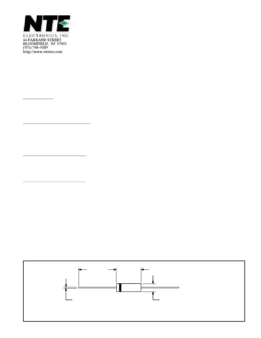
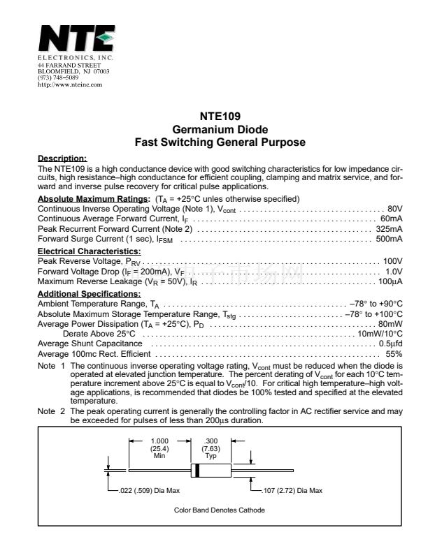
1.000
(25.4)
Min
.300
(7.63)
Typ
.022 (.509) Dia Max
.107 (2.72) Dia Max
Color Band Denotes Cathode


 1
1
