鈾?/div>
High temperature soldering guaranteed:
250擄C, 0.25" (6.35mm) from case for 10 seconds
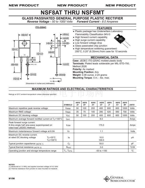
0.600 (15.5)
0.580 (14.5)
0.676 (17.2)
0.646 (16.4)
2
0.350 (8.89)
0.330 (8.38)
PIN
1
0.191 (4.85)
0.171 (4.35)
0.560 (14.22)
0.530 (13.46)
0.060 (1.52)
0.110 (2.80)
0.100 (2.54)
MECHANICAL DATA
Case:
JEDEC ITO-220AC molded plastic body
Terminals:
Plated leads solderable per MIL-STD-750,
Method 2026
Polarity:
As marked
Mounting Position:
Any
Weight:
0.08 ounce, 2.24 grams
Mounting Torque:
5 in. - lbs. max.
0.037 (0.94)
0.027 (0.69)
0.205 (5.20)
0.195 (4.95)
PIN 1
PIN 2
0.022 (0.55)
0.014 (0.36)
Dimensions in inches and (millimeters)
MAXIMUM RATINGS AND ELECTRICAL CHARACTERISTICS
Ratings at 25擄C ambient temperature unless otherwise specified.
SYMBOLS
NSF8
AT
NSF8
BT
NSF8
DT
NSF8
GT
NSF8
JT
NSF8
KT
NSF8
MT
UNITS
Maximum repetitive peak reverse voltage
Maximum RMS voltage
Maximum DC blocking voltage
Maximum average forward rectified current at T
C
=100擄C
Peak forward surge current
8.3ms single half sine-wave superimposed on
rated load (JEDEC Method)
Maximum instantaneous forward voltage at 8.0A
Maximum DC reverse current
at rated DC blocking voltage
Typical junction capacitance
Typical thermal resistance
(NOTE 1)
V
RRM
V
RMS
V
DC
I
(AV)
I
FSM
V
F
I
R
C
J
R
螛JC
T
J
, T
STG
50
35
50
100
70
100
200
140
200
400
280
400
8.0
175.0
1.1
10.0
100.0
55.0
3.0
-55 to +150
600
420
600
800
560
800
1000
700
1000
Volts
Volts
Volts
Amps
Amps
Volts
碌A(chǔ)
pF
擄C/W
擄C
T
C
=25擄C
T
C
=100擄C
(NOTE 2)
Operating junction and storage temperature range
NOTES:
(1) Measured at 1.0 MH
Z
and applied reversed voltage of 4.0 Volts
(2) Thermal resistance from junction to case mounted on heatsink
9/1/98


 1
1
 2
2
