V.
飩?/div>
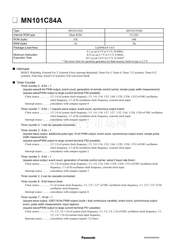
Interrupts
RESET, Watchdog, External
0
to
2,
External
4
(key interrupt dedicated), Timer
0
to
3,
Timer
6,
Timer
7
(2 systems), Timer
8
(2
systems), Time base, Serial
0
(2 systems), A/D conversion 鏗乶ish
Timer counter
0
:
8-bit
脳
1
(square-wave/8-bit PWM output, event count, generation of remote control carrier, simple pulse width measurement)
(square-wave/PWM output to large current terminal P50 possible)
Clock source................
1/2, 1/4
of system clock frequency;
1/1, 1/4, 1/16, 1/32, 1/64, 1/128, 1/256, 1/512
of OSC oscillation
clock frequency;
1/1
of XI oscillation clock frequency; external clock input
Interrupt source ........... coincidence with compare register
0
Timer counter
1
:
8-bit
脳
1
(square-wave output, event count, synchronous output event)
Clock source................
1/2, 1/8
of system clock frequency;
1/1, 1/4, 1/16, 1/2
13
,
1/2
15
,
1/32, 1/64, 1/128, 1/256
of OSC oscillation
clock frequency;
1/1
of XI oscillation clock frequency; external clock input
Interrupt source ........... coincidence with compare register
1
Timer counter
0, 1
can be cascade-connected.
飩?/div>
Timer Counter
Timer counter
2
:
8-bit
脳
1
(square-wave output, additional pulse type
10-bit
PWM output, event count, synchronous output event, simple pulse
width measurement)
(square-wave/PWM output to large current terminal P52 possible)
Clock source................
1/2, 1/4
of system clock frequency;
1/1, 1/4, 1/16, 1/32, 1/64, 1/128, 1/256, 1/512
of OSC oscillation
clock frequency;
1/1
of XI oscillation clock frequency; external clock input
Interrupt source ........... coincidence with compare register
2
Timer counter
3
:
8-bit
脳
1
(square-wave output, event count, generation of remote control carrier, serial
0
baud rate timer)
Clock source................
1/2, 1/8
of system clock frequency;
1/1, 1/4, 1/16, 1/64, 1/128, 1/256, 1/512
of OSC oscillation clock
frequency;
1/1
of XI oscillation clock frequency; external clock input
Interrupt source ........... coincidence with compare register
3
Timer counter
2, 3
can be cascade-connected.
Timer counter
6
:
8-bit
freerun timer
Clock source................
1/1
of system clock frequency;
1/1, 1/2
12
,
1/2
13
of OSC oscillation clock frequency;
1/1, 1/2
12
,
1/2
13
of XI
oscillation clock frequency
Interrupt source ........... coincidence with compare register
6
Timer counter
7
:
16-bit
脳
1
(square-wave output, IGBT/16-bit PWM output (cycle / duty continuous variable), event count, synchronous output
evevt, pulse width measurement, input capture)
(square-wave/PWM output to large current terminal P51 possible)
Clock source................
1/1, 1/2, 1/4, 1/16
of system clock frequency;
1/1, 1/2, 1/4, 1/16
of OSC oscillation clock frequency;
1/1,
1/2, 1/4, 1/16
of external clock input frequency
Interrupt source ........... coincidence with compare register
7
(2 lines)
MAD00049DEM


 1
1
 2
2
 3
3
 4
4
