19-4771; Rev 1; 10/98
MAX769 Evaluation Kit
General Description
The MAX769 evaluation kit (EV kit) provides a platform for
evaluating the features of the MAX769. The MAX769 con-
verts a 2-cell or 3-cell, 1.5V to 5.5V battery voltage to four
separate output voltages. The main output voltage at
OUT is digitally controlled from 1.8V to 4.9V in 100mV
steps by a 3-wire SPI鈩?serial interface. OUT provides up
to 80mA. The other outputs (REG1, REG2, and REG3)
are low-noise linear-regulator outputs. The MAX769 con-
tains numerous other features for two-way paging and
other low-power wireless designs. Consult the MAX769
data sheet for details. The MAX769 EV kit is a fully
assembled and tested surface-mount circuit board.
The MAX847 is similar to the MAX769 except that it
contains a boost DC-DC converter (for 1-cell inputs)
rather than a buck-boost converter (for 2-cell or 3-cell
inputs). To evaluate the MAX847, please order the
MAX847EVKIT.
Features
o
1.5V to 5.5V (buck-boost) Input Voltage
o
1.8V to 4.9V Digitally Adjustable Output Voltage
o
Up to 80mA Total Output Current
o
Three Low-Noise Voltage Regulators
o
Charger for Small NiCd, NiMH, Lithium Battery, or
Storage Capacitor
o
270kHz Switching Frequency
o
15碌A(chǔ) Idle Mode鈩?Current
o
Digitally Controlled 1.8鈩?Switches for Vibrators,
Beepers, and Other Low-Power Wireless Designs
o
Reset and Low-Battery Outputs
o
Surface-Mount Components
o
Fully Assembled and Tested
Evaluates: MAX769
Ordering Information
PART
MAX769EVKIT
TEMP. RANGE
0擄C to +70擄C
IC PACKAGE
28 QSOP
Component List
DESIGNATION QTY
C1, C2
C3, C8, C10,
C12, C13, C15,
C16
C4
C5, C9, C14
C6, C7
C11
D1
R1
R2, R3, R6, R8,
R11, R13, R18,
R22
R4, R7, R9,
R10, R17, R19,
R20, R23
2
DESCRIPTION
47碌F, 16V low-ESR tantalum caps
Sprague 593D476X0016E2W or
AVX TPSD476M016R0150
0.1碌F ceramic capacitors
22nF ceramic capacitor
1碌F ceramic capacitors
10碌F, 10V tantalum capacitors
Sprague 595D106X0010A2T
1000pF ceramic capacitor
0.5A, 20V Schottky diode (optional)
Motorola MBR0520L
15k鈩? 5% resistor
1k鈩? 5% resistors
SW1鈥揝W4
8
100k鈩? 5% resistors
LED1
None
None
4
1
1
1
L1
U1
JU1鈥揓U10
JU11
JU12
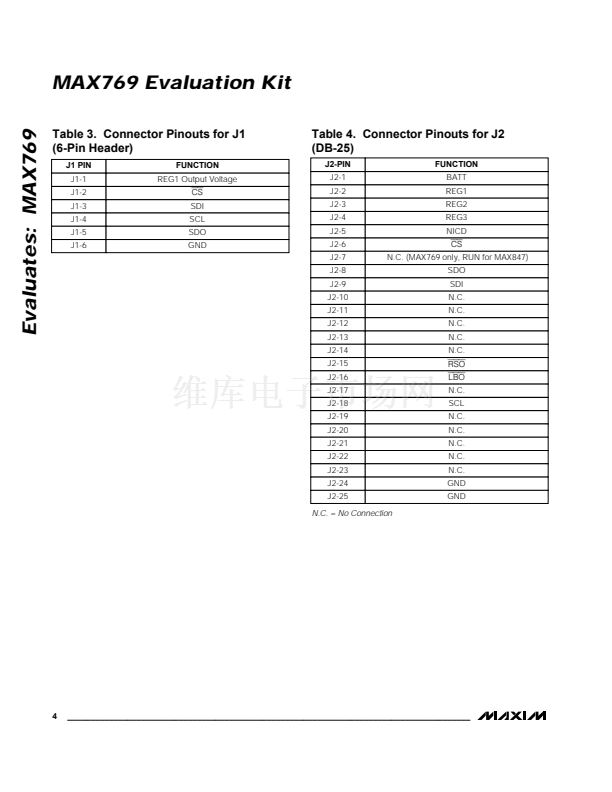
J1
J2
8
1
1
10
1
1
1
1
DESIGNATION QTY
R5
R12
R15
7
1
3
2
1
0
1
R14, R16
R21
1
1
1
2
1
DESCRIPTION
100k鈩? 5% resistor
390k鈩? 5% resistor
1M鈩? 5% resistor
620k鈩? 5% resistors
10k鈩? 5% resistor
68碌H inductor
Sumida CD54-680
MAX769EEI
2-pin headers
3-pin header
4-pin header
6-pin header
25-pin, female, right-angle connector
Slide switches
Mouser 10SP001
Green light-emitting diode
MAX847/MAX769 PC board
MAX769 data sheet
Idle Mode is a trademark of Maxim Integrated Products.
SPI is a trademark of Motorola Corp.
________________________________________________________________
Maxim Integrated Products
1
For free samples & the latest literature: http://www.maxim-ic.com, or phone 1-800-998-8800.
For small orders, phone 1-800-835-8769.


 1
1
 2
2
 3
3
 4
4
 5
5
 6
6
 7
7
 8
8
