19-1369; Rev 0; 7/98
MAX4188 Evaluation Kit
General Description
The MAX4188 evaluation kit (EV kit) simplifies evalua-
tion of the MAX4188 triple, low-power, current-feedback
amplifier. The MAX4188 amplifier is set to a gain of
+2V/V. SMA connectors and 50鈩?terminating resistors
are included for 50鈩?test equipment compatibility. For
video test equipment compatibility, simply change the
terminating resistors to 75鈩?and change R
F
and R
G
resistors to the values shown in the MAX4188/
MAX4189/MAX4190 data sheet.
The EV kit comes with the MAX4188 installed. To evaluate
the MAX4189, order a free sample (MAX4189ESD),
replace the MAX4188 with the MAX4189 on the EV board,
and change the gain-setting and feedback resistors for
unity gain as shown in the MAX4188/MAX4189/
MAX4190 data sheet.
____________________________Features
o
Fast Enable/Disable Times (120ns/35ns)
o
Very Low Switching Transient (45mVp-p)
o
Single +5V or Dual 鹵5V Supply Operation
o
130MHz -3dB Bandwidth
o
350V/碌s Slew Rate
o
70MHz -0.1dB Gain Flatness
o
0.04%/0.32% Gain/Phase Errors (R
L
= 150鈩?
o
Fully Assembled and Tested Surface-Mount Board
Evaluates: MAX4188/MAX4189
____________________________Component List
DESIGNATION QTY
C1, C4
C2, C5
C3, C6
R1鈥揜6
RF1, RF2, RF3,
RG1, RG2,
RG3
IN1+, IN2+,
IN3+, OUT1,
OUT2, OUT3
JU1, JU2, JU3
U1
None
None
2
2
2
6
6
DESCRIPTION
10碌F, 10V, 20% tantalum capacitors
AVX TAJB106M010 or
Sprague 293D106X0010B
0.33碌F, 10% ceramic capacitors
0.01碌F, 10% ceramic capacitors
49.9鈩? 1% resistors
_______________Ordering Information
PART**
MAX4188EVKIT
TEMP. RANGE
-40擄C to +85擄C
IC PACKAGE
14 SO
**To
evaluate the MAX4189, request a MAX4189ESD sample.
Quick Start
390鈩? 1% resistors
6
3
1
1
3
SMA connectors
2-pin header
MAX4188ESD
MAX4188 EV kit PC board
Shunts for JU1, JU2, JU3
Component Suppliers
SUPPLIER*
AVX
Sprague
PHONE
(803) 946-0690
(603) 224-1961
FAX
(803) 626-3123
(603) 224-1430
The MAX4188 EV kit is fully assembled and tested.
Follow these steps to verify board operation.
1) The circuit requires supply voltages of 鹵2.25V to
鹵5.5V. For evaluation purposes, connect a +5V sup-
ply to the pad labeled VCC and a -5V supply to the
pad labeled VEE. Connect power-supply ground to
the pad labeled GND.
2) Connect an output (OUT1鈥揙UT3) to an oscilloscope
input. Remove shunt from the corresponding jumper
(JU1鈥揓U3) to enable the selected amplifier.
3) Turn on the power supply. Apply a 鹵1.35V signal to
the appropriate amplifier input (IN1鈥揑N3). The 100鈩?/div>
load (chosen for ease of evaluation) limits the output
voltage range. Wider output voltage swings are
achievable with lighter loads. See the MAX4188/
MAX4189/MAX4190 data sheet.
4) Verify the output signal on the oscilloscope.
*Please
indicate that you are using the MAX4188 when contact-
ing these component suppliers.
________________________________________________________________
Maxim Integrated Products
1
For free samples & the latest literature: http://www.maxim-ic.com, or phone 1-800-998-8800.
For small orders, phone 408-737-7600 ext. 3468.


 1
1
 2
2
 3
3
 4
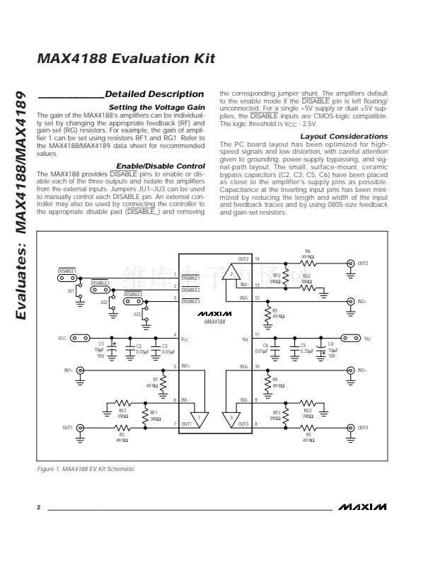
4
