19-2594; Rev 1; 11/02
MAX1926 Evaluation Kit
General Description
The MAX1926 evaluation kit (EV kit) is a complete, fully
assembled and tested, single-cell lithium-ion (Li+) bat-
tery charger. The EV kit provides a 4.2V output from
input as high as 12V, and delivers up to 1A charge cur-
rent. A light-emitting diode (LED) indicates the cell鈥檚
charging status.
The EV kit can be also used to evaluate the MAX1925,
which is a single-cell Li+ battery charger with a 4.5V to
6.1V input voltage charge range.
o
5V to 12V Input Voltage Range
o
Up to 1A Fast Charge Current
o
LED Charge Status and Fault Indicator
o
12-Pin Thin QFN Package
o
Surface-Mount Construction
o
Fully Assembled and Tested
Features
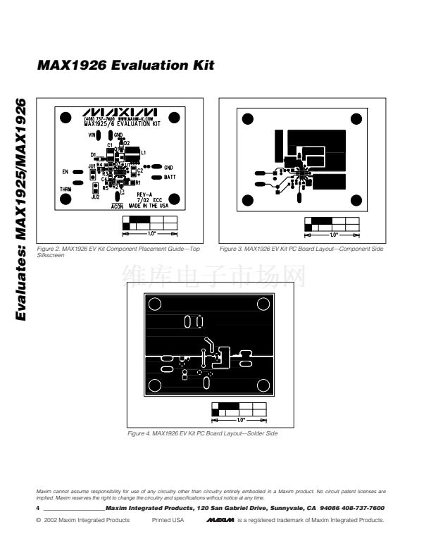
Evaluates: MAX1925/MAX1926
Component List
DESIGNATION QTY
1
DESCRIPTION
10碌F 鹵20%, 16V X5R
ceramic capacitor (1210)
Taiyo Yuden EMK325BJ106MN or
TDK C3225X5R1C106MT
22碌F 鹵20%, 6.3V tantalum capacitor
(A case)
AVX TAJA226M006R
0.1碌F 鹵10%, 16V X7R
ceramic capacitor (0603)
Taiyo Yuden EMK107BJ104KA or
TDK C1608X7R1C104KT or
Murata GRM39X7R104K016AD
Not installed, capacitor (0603)
1A, 30V Schottky diodes
Nihon EP10QY03
Surface-mount LED (0805)
2-pin header
Not installed, shorted by PC trace
10碌H, 1.3A inductor
Toko A915AY-100M or
Sumida CDRH5D28-100
P-channel MOSFET 3-pin SOT23
Fairchild FDN360P
0.14鈩?鹵1%, 1/2W sense resistor
(1206)
IRC LR1206-01-R140-F
100k鈩?鹵5% resistor (0603)
Not installed, resistors (0603)
10k鈩?鹵5% resistor (0603)
MAX1926ETC 12-pin thin QFN
4mm
x
4mm, top mark AABF
Shunt
MAX1926 PC board
PART
Ordering Information
TEMP RANGE IC PACKAGE
MAX1926EVKIT 0擄C to +70擄C 12 Thin QFN 4mm x 4mm
Note:
To evaluate the MAX1925, request a MAX1925 free sam-
ple with the MAX1926EVKIT.
C1
C2
1
Quick Start
The MAX1926 EV kit is a fully assembled and tested
surface-mount board. Follow the steps below to verify
board operation.
Do not turn on the power supply
until all connections are completed:
1) Verify that there is a no shunt across jumper JU1 (EN).
2) Connect a voltmeter across the EV kit鈥檚 BATT and
GND pads.
3) Connect a 5V to 12V power supply to the VIN pad.
Connect the power-supply ground to the GND pad
closest to VIN.
4)
Observe correct Li+ cell polarity.
Connect the pos-
itive terminal of a single-cell Li+ battery to the BATT
pad. Connect the negative terminal of the battery to
the GND pad closest to BATT.
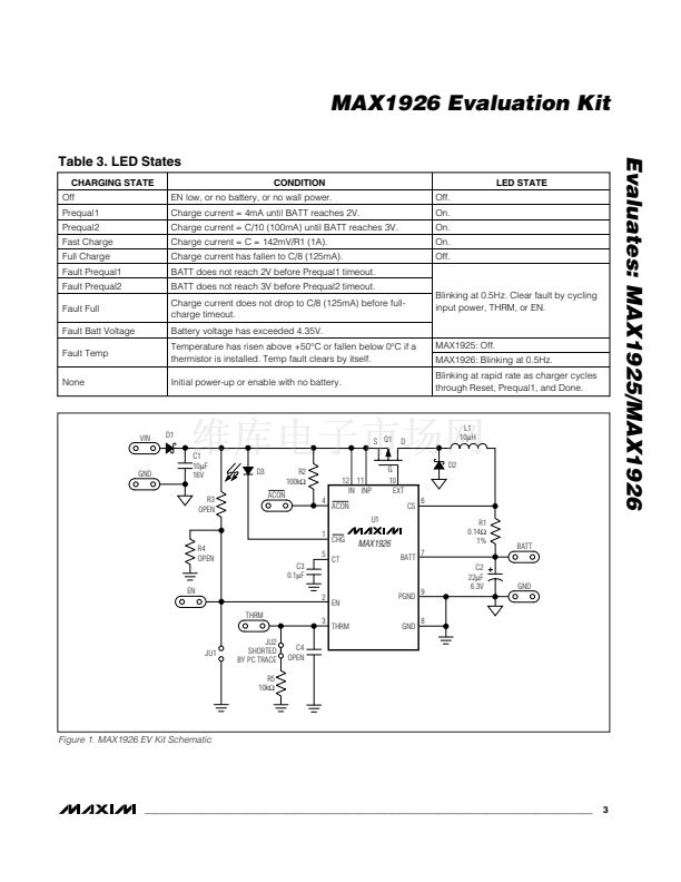
5) Turn on the power supply. The LED turns on if the
battery voltage is below 4.2V and the charging cur-
rent is above 125mA. See Table 3 for additional LED
state descriptions.
6) The LED turns off once the Li+ cell has been fully
charged.
To evaluate the MAX1925, see the
Evaluating the
MAX1925
section.
C3
1
C4
D1, D2
D3
JU1
JU2
L1
Q1
R1
R2
R3, R4
R5
U1
None
None
0
2
1
1
0
1
1
1
1
0
1
1
1
1
________________________________________________________________
Maxim Integrated Products
1
For pricing, delivery, and ordering information, please contact Maxim/Dallas Direct! at
1-888-629-4642, or visit Maxim鈥檚 website at www.maxim-ic.com.


 1
1
 2
2
 3
3
 4
4
