19-1660; Rev 0; 8/00
MAX1760 Evaluation Kit
General Description
The MAX1760 evaluation kit (EV kit) is a fully assembled
and tested surface-mount circuit board that contains a
boost switching-regulator circuit. The EV kit provides a
regulated +3.3V output at up to 800mA of current. The
input voltage range is +0.7V to +5.5V. However, the
output voltage will rise above the regulation point for
input voltages exceeding 3.3V. A one- or two-cell bat-
tery input can also be used to power the EV kit.
The MAX1760 features an internal N-channel MOSFET
switch, a synchronous rectifier, and a pin-selectable
forced PWM mode. The MAX1760 EV kit demonstrates
low quiescent current and power efficiency up to 96%,
thus increasing battery life. Operation at 1MHz allows
the use of tiny surface-mount components.
o
+0.7V to +5.5V Input Voltage
o
+3.3V Output Voltage
o
Internal Synchronous Rectifier Provides up to
96% Efficiency
o
Output is Adjustable with External Resistors
o
Up to 800mA Output
o
On-Chip N-Channel Switch
o
1碌A Shutdown Current
o
1MHz Switching Frequency
o
Fixed-Frequency PWM Operation
o
Surface-Mount Components
o
Fully Assembled and Tested
Features
Evaluates: MAX1760
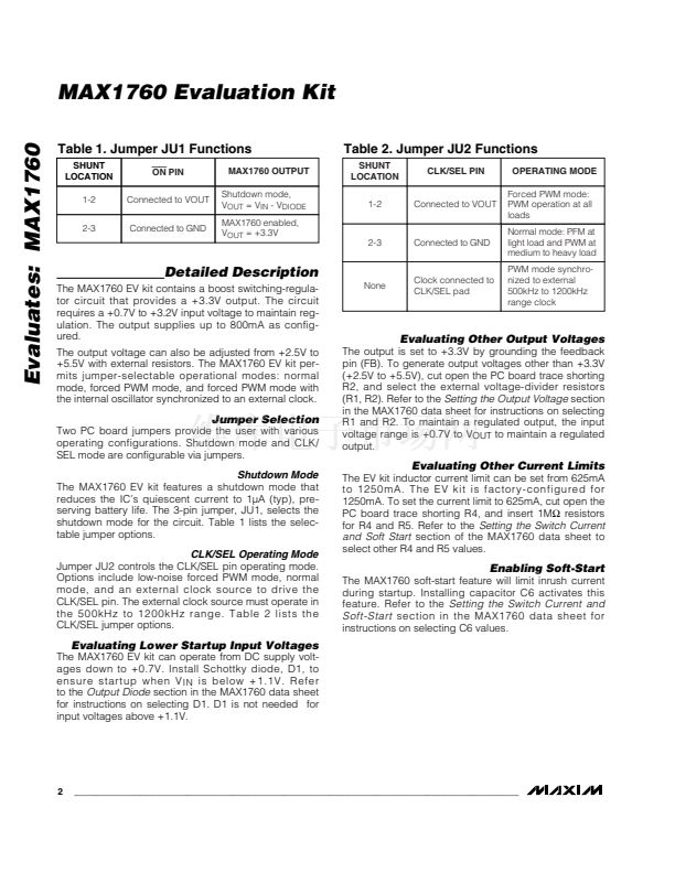
Component List
DESIGNATION QTY
C1
C2
C3
C4
C5
C6
D1
L1
R3
R1, R2, R4, R5
U1
JU1, JU2
None
None
None
None
1
1
1
1
1
0
1
1
1
0
1
2
2
1
1
1
DESCRIPTION
33碌F, 16V, low-ESR electrolytic cap
Sanyo 16TPC33M
100碌F, 6.3V, low-ESR electrolytic cap
Sanyo 6TPC100M
1碌F, 10V, X5R ceramic cap (0805)
Taiyo Yuden LMK212BJ105MG
0.68碌F, 10V, X5R ceramic cap (0805)
Taiyo Yuden LMK212BJ684KG
0.22碌F, 25V, X7R ceramic cap (1206)
Taiyo Yuden TMK316BJ224KF
Not installed (0805)
Not installed, Nihon EP10QY03
3.3碌H, 1.4A inductor
Coilcraft DO1606T-332
4.7鈩?鹵5% resistor (0805)
Not installed (0805)
Maxim MAX1760EUB (10-pin 碌MAX)
3-pin headers
Shunts (JU1, JU2)
MAX1760 PC board
MAX1760 data sheet
MAX1760 EV kit data sheet
SUPPLIER
Coilcraft
Nihon USA
Sanyo USA
Taiyo Yuden
PART
MAX1760EVKIT
Ordering Information
TEMP. RANGE
0擄C to +70擄C
IC PACKAGE
10 碌MAX
Component Suppliers
PHONE
847-639-6400
661-867-2555
619-661-6835
408-573-4150
FAX
847-639-1469
661-867-2698
619-661-1055
408-573-4159
Note:
Please indicate that you are using the MAX1760 when
contacting these component suppliers.
Quick Start
The MAX1760 EV kit is fully assembled and tested.
Follow these steps to verify board operation for a +3.3V
output.
Do not turn on the power supply until all con-
nections are completed.
1) Connect a +1.1V to +3.2V DC power supply to the
VIN pad. Connect the supply ground to the GND
pad.
2) Connect a voltmeter to the VOUT pad.
3) Verify that jumper JU1 (ON) has a shunt across pins
2 and 3 and jumper JU2 (CLK/SEL) has a shunt
across pins 1 and 2.
4) Turn on the power supply and verify that the main
output is +3.3V.
________________________________________________________________
Maxim Integrated Products
1
For free samples and the latest literature, visit www.maxim-ic.com or phone 1-800-998-8800.
For small orders, phone 1-800-835-8769.


 1
1
 2
2
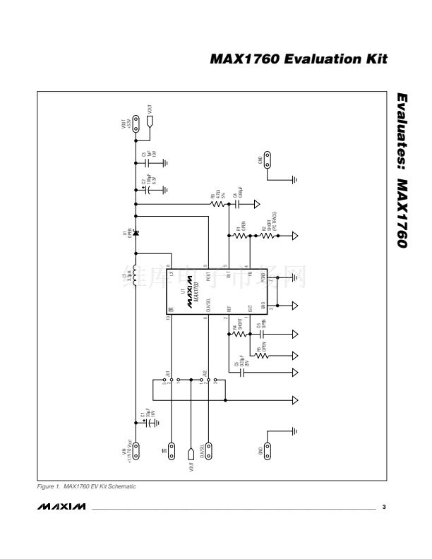 3
3
 4
4
