19-2810; Rev 0; 4/03
MAX1565 Evaluation Kit
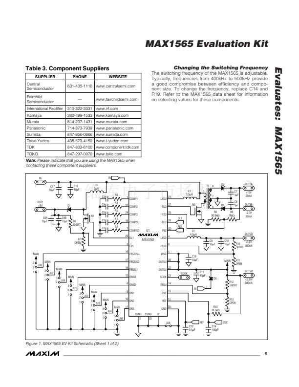
General Description
The MAX1565 evaluation kit (EV kit) is a fully assembled
and tested circuit board that accepts 1.5V to 3.6V input
voltages and provides all the output voltages required
for a typical digital still camera. The outputs consist of
the main step-up output (3.35V), a step-down output
(1.5V), a general-purpose 5V output, two outputs for
charge-coupled device (CCD) and LCD bias, and an
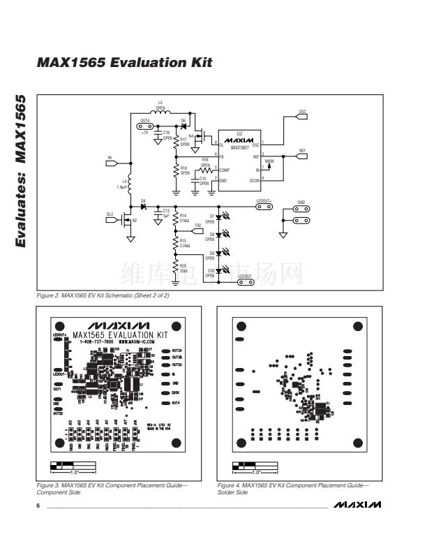
optional general-purpose output using the MAX1801
slave controller.
o
o
o
o
o
o
o
o
Features
95% Efficiency
1.5V to 3.6V Input Voltage Range
Main Step-Up Output: 3.35V or Adjustable
Step-Down Output: 1.5V or Adjustable
5V General-Purpose Output
CCD and LCD Bias Outputs (+15V/-7.5V)
Power-Regulated Output for White LED
Backlighting
Optional General-Purpose Output Using the
MAX1801 Slave Controller
1碌A(chǔ) Shutdown Mode
Internal Soft-Start Control
Overload Protection for All Outputs
Fully Assembled and Tested
Evaluates: MAX1565
Component List
DESIGNATION QTY
DESCRIPTION
6800pF, 25V X7R ceramic capacitor
(0402)
Murata GRP155R71E682K or
equivalent
3300pF, 50V X7R ceramic capacitor
(0402)
Murata GRP155R71H332K or
equivalent
0.01碌F, 25V X7R ceramic capacitor
(0402)
Murata GRP155R71E103K or
equivalent
1000pF, 50V X7R ceramic capacitors
(0402)
Murata GRP155R71H102K or
equivalent
10碌F, 10V X5R ceramic capacitors
(1210)
Taiyo Yuden LMK325BJ106MN or
equivalent
1碌F, 25V X7R ceramic capacitors
(1206)
TDK C3216X7R1E105K or equivalent
10碌F, 6.3V X5R ceramic capacitors
(0805)
Panasonic ECJ2FB0J106M or
Taiyo Yuden JMK212BJ106MG
47碌F, 6.3V X5R ceramic capacitor
(1812)
Taiyo Yuden JMK432BJ476MM
0.1碌F, 16V X7R ceramic capacitor
(0603)
Taiyo Yuden EMK107BJ104MA or
equivalent
C1
1
o
o
o
o
Ordering Information
PART
MAX1565EVKIT
TEMP RANGE
-40擄C to +85擄C
IC PACKAGE
32 Thin QFN 5mm
鉁?/div>
5mm
C2
1
Quick Start
Follow the steps below to verify operation of the
MAX1565 EV kit.
Do not turn on the power supply until
all connections are completed:
1) Connect a series LED array or install surface-mount
white LEDs in D7鈥揇10. When connecting an LED
array, connect the anode to LEDOUT+ and connect
the cathode to LEDOUT-.
2) Preset the power supply to between 1.5V and 3.6V.
3) Turn off the power supply.
4) Connect the power-supply positive lead to IN.
5) Connect the power-supply ground lead to GND.
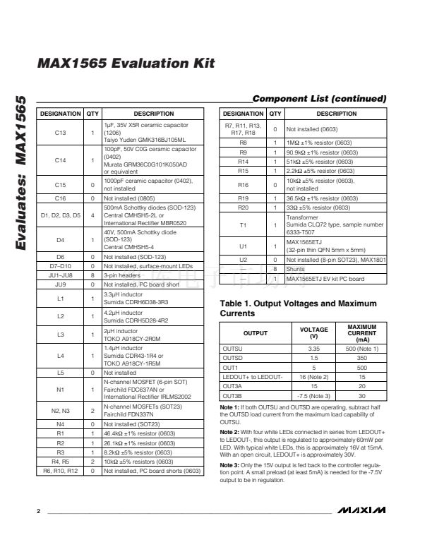
6) Connect loads from outputs OUTSD, OUT1, OUT3A,
and OUT3B to GND. See Table 1 for maximum load
currents.
7) To enable the main step-up output, verify that JU1
has pins 2 and 3 shorted.
8) Verify that JU2鈥揓U8 have pins 1 and 2 shorted.
9) Turn on the power supply.
10) Use a voltmeter to verify the OUTSU voltage (3.35V).
11) Connect a load, if desired, from OUTSU to GND.
See Table 1 for maximum load currents.
12) To verify other outputs, move JU2鈥揓U5 to short pins
2 and 3. Use a voltmeter to verify output voltages.
1
C3
1
C4, C5
2
C6A, C6B
2
C7, C8
2
C9, C10, C17,
C18, C19
5
C11
1
C12
1
________________________________________________________________
Maxim Integrated Products
For pricing, delivery, and ordering information, please contact Maxim/Dallas Direct! at
1-888-629-4642, or visit Maxim鈥檚 website at www.maxim-ic.com.


 1
1
 2
2
 3
3
 4
4
 5
5
 6
6
 7
7
