Dim.
Min.
Max.
鈩?/div>
ambient temperature unless otherwise specified.
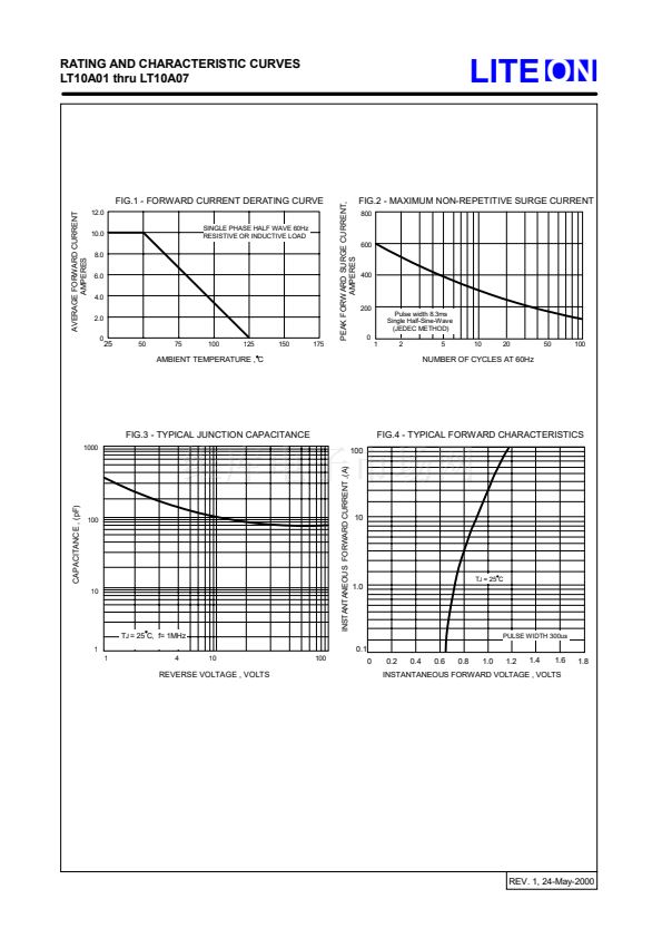
Single phase, half wave, 60Hz, resistive or inductive load.
For capacitive load, derate current by 20%
CHARACTERISTICS
Maximum Recurrent Peak Reverse Voltage
Maximum RMS Voltage
Maximum DC Blocking Voltage
Maximum Average Forward
Rectified Current
SYMBOL
LT10A01 LT10A02 LT10A03 LT10A04 LT10A05 LT10A06 LT10A07
UNIT
V
RRM
V
RMS
V
DC
I
(AV)
50
35
50
100
70
100
200
140
200
400
280
400
10.0
600
1.0
10
100
150
10
-55 to +125
-55 to +150
600
420
600
800
560
800
1000
700
1000
V
V
V
A
@T
A
=
50 C
Peak Forward Surge Current
8.3ms single half sine-wave
super imposed on rated load (JEDEC Method)
Maximum forward Voltage at 10A DC
Maximum DC Reverse Current
at Rated DC Blocking Voltage
Typical Junction
Capacitance (Note 1)
Typical Thermal Resistance (Note 2)
Operating Temperature Range
Storage Temperature Range
I
FSM
V
F
I
R
C
J
R
0JA
A
V
uA
pF
C/W
@T
J
=25 C
@T
J
=100 C
T
J
T
STG
C
C
REV. 1, 24-May-2000
NOTES : 1.Measured at 1.0MHz and applied reverse voltage of 4.0V DC.
2.Thermal Resistance Junction to Ambient.


 1
1
 2
2
