IFE80-06
FULL POWER
SEMICONDUCTOR
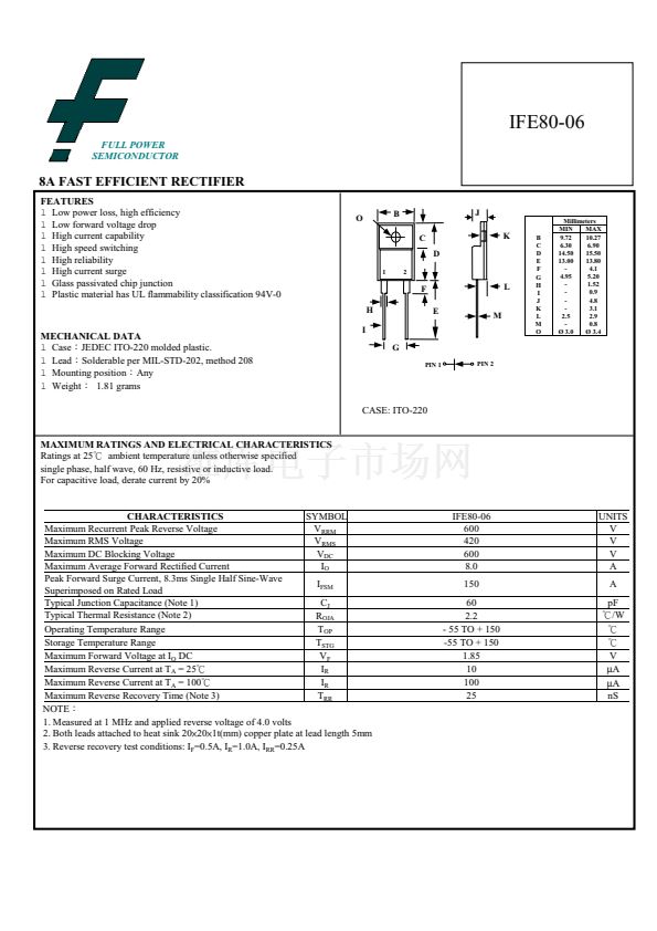
8A FAST EFFICIENT RECTIFIER
FEATURES
l
Low power loss, high efficiency
l
Low forward voltage drop
l
High current capability
l
High speed switching
l
High reliability
l
High current surge
l
Glass passivated chip junction
l
Plastic material has UL flammability classification 94V-0
O
B
C
D
1
2
J
K
B
C
D
E
F
G
H
I
J
K
L
M
O
Millimeters
MIN
MAX
9.72
10.27
6.30
6.90
15.50
14.50
13.00
13.80
-
4.1
4.95
5.20
-
1.52
-
0.9
-
4.8
-
3.1
2.5
2.9
-
0.8
脴 3.0
脴 3.4
F
H
E
M
L
MECHANICAL DATA
l
Case錛欽EDEC ITO-220 molded plastic.
l
Lead錛歋olderable per MIL-STD-202, method 208
l
Mounting position錛欰ny
l
Weight錛?1.81 grams
I
G
PIN 1
PIN 2
CASE: ITO-220
MAXIMUM RATINGS AND ELECTRICAL CHARACTERISTICS
Ratings at 25鈩?ambient temperature unless otherwise specified
single phase, half wave, 60 Hz, resistive or inductive load.
For capacitive load, derate current by 20%
SYMBOL
CHARACTERISTICS
Maximum Recurrent Peak Reverse Voltage
V
RRM
Maximum RMS Voltage
V
RMS
Maximum DC Blocking Voltage
V
DC
Maximum Average Forward Rectified Current
I
O
Peak Forward Surge Current, 8.3ms Single Half Sine-Wave
I
FSM
Superimposed on Rated Load
Typical Junction Capacitance (Note 1)
C
J
Typical Thermal Resistance (Note 2)
R
OJA
Operating Temperature Range
T
OP
Storage Temperature Range
T
STG
Maximum Forward Voltage at I
O
DC
V
F
I
R
Maximum Reverse Current at T
A
= 25鈩?/div>
I
R
Maximum Reverse Current at T
A
= 100鈩?/div>
Maximum Reverse Recovery Time (Note 3)
T
RR
NOTE錛?/div>
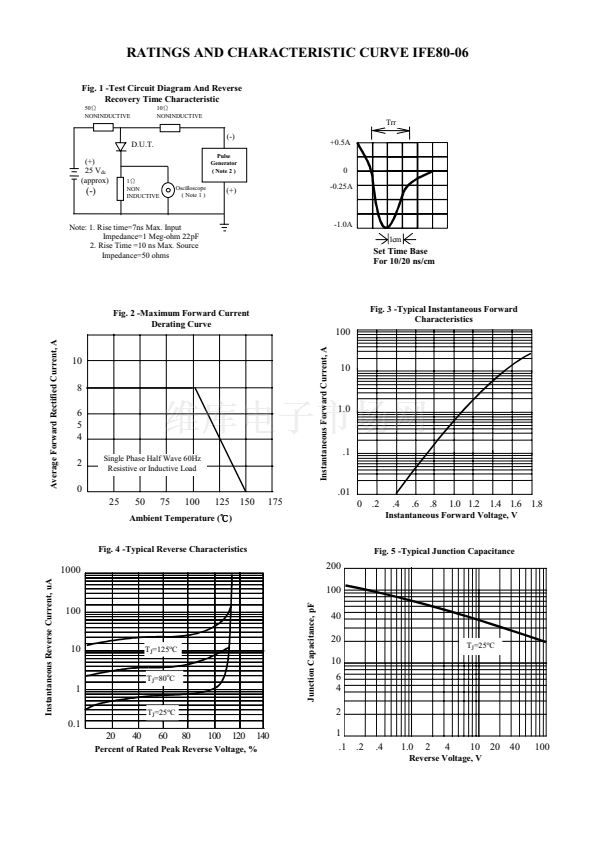
1. Measured at 1 MHz and applied reverse voltage of 4.0 volts
2. Both leads attached to heat sink 20脳20脳1t(mm) copper plate at lead length 5mm
3. Reverse recovery test conditions: I
F
=0.5A, I
R
=1.0A, I
RR
=0.25A
IFE80-06
600
420
600
8.0
150
60
2.2
- 55 TO + 150
-55 TO + 150
1.85
10
100
25
UNITS
V
V
V
A
A
pF
鈩?W
IFE80-06相關(guān)型號(hào)PDF文件下載


 1
1
 2
2
