S E M I C O N D U C T O R
January 1998
NOT
RN
D FO 36
DE
MEN e ICL71
OM Se
REC
EW
IG
DES
NS
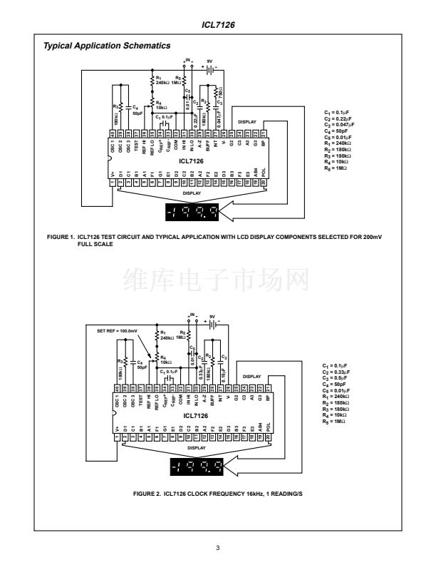
ICL7126
3
1
/
2
Digit, Low Power,
Single-Chip A/D Converter
Features
鈥?8,000 Hours Typical 9V Battery Life
鈥?Guaranteed Zero Reading for 0V Input on All Scales
鈥?True Polarity at Zero for Precise Null Detection
鈥?1pA Typical Input Current
鈥?True Differential Input and Reference
鈥?Direct LCD Display Drive - No External Components
Required
鈥?Pin Compatible With the ICL7106
鈥?Low Noise - Less Than 15碌V
P-P
鈥?On-Chip Clock and Reference
鈥?Low Power Dissipation Guaranteed Less Than 1mW
鈥?No Additional Active Circuits Required
Description
The ICL7126 is a high performance, very low power
3
1
/
2
-digit, A/D converter. All the necessary active devices
are contained on a single CMOS IC, including seven seg-
ment decoders, display drivers, reference, and clock. The
ICL7126 is designed to interface with a liquid crystal display
(LCD) and includes a backplane drive. The supply current of
100碌A(chǔ) is ideally suited for 9V battery operation.
The ICL7126 brings together an unprecedented combination
of high accuracy, versatility, and true economy. It features
auto-zero to less than 10碌V, zero drift of less than 1碌V/
o
C,
input bias current of 10pA maximum, and rollover error of
less than one count. The versatility of true differential input
and reference is useful in all systems, but gives the designer
an uncommon advantage when measuring load cells, strain
gauges and other bridge-type transducers. And 鏗乶ally the
true economy of single power operation allows a high
performance panel meter or multi-meter to be built with the
addition of only 10 passive components and a display.
The ICL7126 can be used as a plug-in replacement for the
ICL7106 in a wide variety of applications, changing only the
passive components.
Ordering Information
PART NUMBER
ICL7126CPL
ICL7126RCPL
TEMP.
RANGE (
o
C)
0 to 70
0 to 70
PACKAGE
40 Ld PDIP
40 Ld PDIP (Note)
PKG.
NO.
E40.6
E40.6
NOTE: 鈥淩鈥?indicates device with reversed leads.
Pinout
ICL7126
(PDIP)
TOP VIEW
V+
D1
C1
B1
(1鈥檚)
A1
F1
G1
E1
D2
C2
(10鈥檚)
B2
A2
F2
E2
D3
(100鈥檚)
B3
F3
E3
(1000) AB4
POL
(MINUS)
1
2
3
4
5
6
7
8
9
10
11
12
13
14
15
16
17
18
19
20
40 OSC 1
39 OSC 2
38 OSC 3
37 TEST
36 REF HI
35 REF LO
34 C
REF
+
33 C
REF
-
32 COMMON
31 IN HI
30 IN LO
29 A-Z
28 BUFF
27 INT
26 V-
25 G2 (10鈥檚)
24 C3
23 A3
22 G3
21 BP/GND
(100鈥檚)
CAUTION: These devices are sensitive to electrostatic discharge. Users should follow proper IC Handling Procedures.
Copyright
漏
Harris Corporation 1998
File Number
3084.3
1


 1
1
 2
2
 3
3
 4
4
 5
5
 6
6
 7
7
 8
8
 9
9
 10
10
 11
11
 12
12
 13
13
 14
14
