HD-4702
March 1997
CMOS Programmable Bit Rate Generator
Description
The HD-4702 Bit Rate Generator provides the necessary clock
signals for digital data transmission systems, such as a UART. It
generates 13 commonly used bit rates using an on-chip crystal
oscillator or an external input. For conventional operation gener-
ating 16 output clock pulses per bit period, the input clock fre-
quency must be 2.4576MHz (i.e. 9600 Baud x 16 x 16, since
there is an internal
梅
16 prescaler). A lower input frequency will
result in a proportionally lower output frequency.
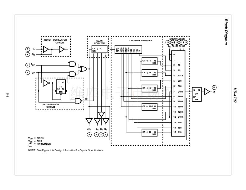
The HD-4702 can provide multi-channel operation with a mini-
mum of external logic by having the clock frequency CO and the
梅
8 prescaler outputs Q0, Q1, Q2 available externally. All signals
have a 50% duty cycle except 1800 Baud, which has less than
0.39% distortion.
The four rate select inputs (S0-S3) select which bit rate is at the
output (Z). See Truth Table for Rate Select Inputs for select code
and output bit rate. Two of the 16 select codes for the HD-4702 do
not select an internally generated frequency, but select an input
into which the user can feed either a different frequency, or a static
level (High or Low) to generate 鈥淶ERO BAUD鈥?
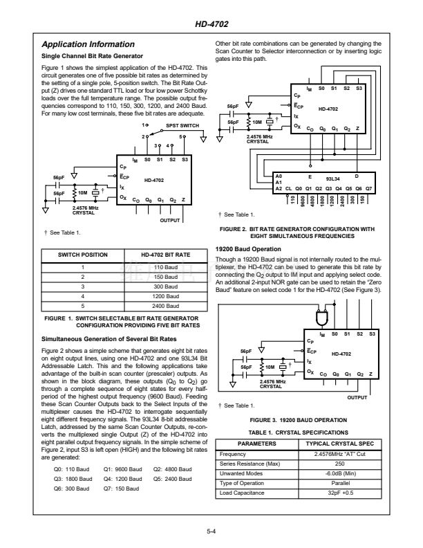
The bit rates most commonly used in modern data terminals
(110, 150, 300, 1200, 2400 Baud) require that no more than one
input be grounded for the HD-4702, which is easily achieved with
a single 5-position switch.
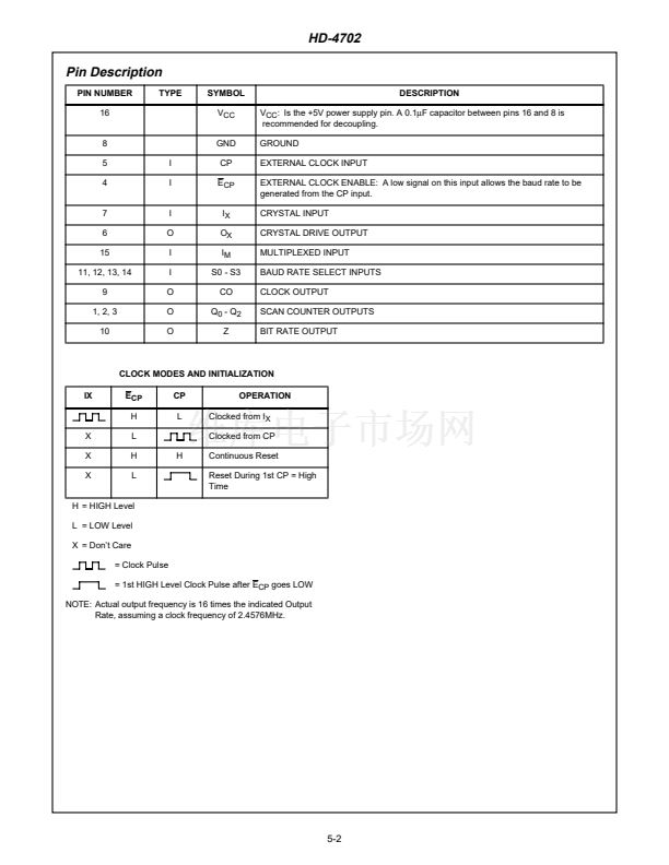
The HD-4702 has an initialization circuit which generates a mas-
ter reset for the scan counter. This signal is derived from a digital
differentiator that senses the 鏗乺st high level on the CP input after
the E
CP
input goes low. When E
CP
is high, selecting the crystal
input, CP must be low. A high level on CP would apply a continu-
ous reset. See Clock Modes and Initialization below.
Features
鈥?HD-4702 Provides 13 Commonly Used Bit Rates
鈥?Uses a 2.4576MHz Crystal/Input for Standard
Frequency Output (16 Times Bit Rate)
鈥?Low Power Dissipation
鈥?Conforms to EIA RS-404
鈥?One HD-4702 Controls up to Eight Transmission
Channels
鈥?Initialization Circuit Facilitates Diagnostic Fault
Isolation
鈥?On-Chip Input Pull-Up Circuit
Ordering Information
PACKAGE
PDIP
CERDIP
SMD#
TEMP.
RANGE (
o
C)
-40 to +85
-40 to +85
-55 to +125
PART NUMBER
HD3-4702-9
HD1-4702-9
5962-9051801MEA
PKG. NO.
E16.3
F16.3
F16.3
Truth Table
TRUTH TABLE FOR RATE SELECT INPUTS
(Using 2.4576MHz Crystal)
S3
L
L
L
L
L
L
L
L
H
H
H
H
H
H
H
H
S2
L
L
L
L
H
H
H
H
L
L
L
L
H
H
H
H
S1
L
L
H
H
L
L
H
H
L
L
H
H
L
L
H
H
S0
L
H
L
H
L
H
L
H
L
H
L
H
L
H
L
H
OUTPUT RATE (Z)
MUX Input (IM)
MUX Input (IM)
50 Baud
75 Baud
134.5 Baud
200 Baud
600 Baud
2400 Baud
9600 Baud
4800 Baud
1800 Baud
1200 Baud
2400 Baud
300 Baud
150 Baud
110 Baud
Pinout
HD-4702 (CERDIP, PDIP)
TOP VIEW
Q0 1
Q1 2
Q2 3
E
CP
4
CP 5
O
X
6
I
X
7
GND 8
16 V
CC
15 I
M
14 S0
13 S1
12 S2
11 S3
10 Z
9 CO
NOTE: 19200 Baud by connecting Q2 to IM.
CAUTION: These devices are sensitive to electrostatic discharge; follow proper IC Handling Procedures.
http://www.intersil.com or 407-727-9207
|
Copyright
漏
Intersil Corporation 1999
File Number
2954.1
5-1


 1
1
 2
2
 3
3
 4
4
 5
5
 6
6
 7
7
