GBL201
THRU
GBL207
Single Phase 2.0 AMPS. Glass Passivated Bridge Rectifiers
Voltage Range
50 to 1000 Volts
Current
2.0 Amperes
Features
Glass passivated chip junction
Ideal for printed circuit board
High case dielectric strength
Plastic material has Underwriters Laboratory
Flammability Classification 94V-0
Typical IR less than 0.1碌A
High surge current capability
High temperature soldering guaranteed:
260
O
C / 10 seconds / .375鈥? (9.5mm) lead
lengths.
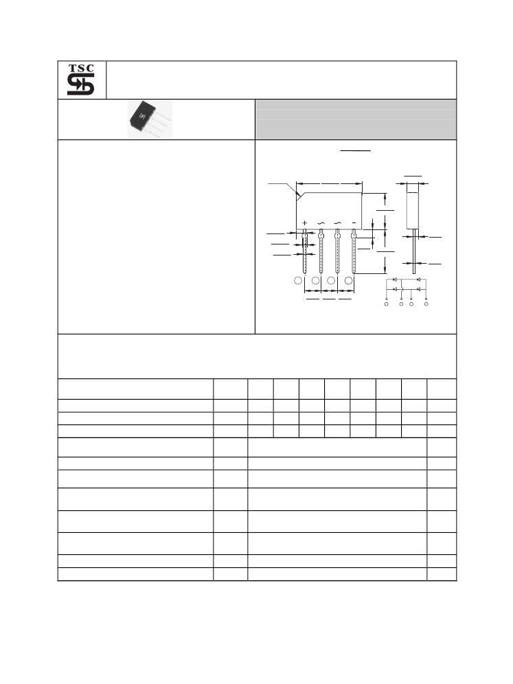
C2.5
.799(20.3)
.776(19.7)
GBL
.146(3.70)
.130(3.30)
.445(11.3)
.421(10.7)
.106(2.70)
.091(2.30)
.067(1.70)
.051(1.30)
.043(1.10)
.035(0.90)
.106(2.70)
.091(2.30)
.047(1.20)
.031(0.80)
.551(14.0)
.512(13.0)
.024(0.60)
.016(0.40)
Mechanical Data
Case: Molded plastic body.
Terminals: Plated leads solderable per
MIL-STD-750, Method 2026.
Weight: 0. 06 ounce, 1.7 grams
Mounting position: Any
1
2
205(5.20)
189(4.80)
3
4
.205(5.20) .205(5.20)
.189(4.80) .189(4.80)
1
2
3
4
Dimensions in inches and (millimeters)
Maximum Ratings and Electrical Characteristics
Rating at 25鈩僡mbient temperature unless otherwise specified.
Single phase, half wave, 60 Hz, resistive or inductive load.
For capacitive load, derate current by 20%
Symbol GBL GBL
Type Number
201 202
50
100
Maximum Recurrent Peak Reverse Voltage
V
RRM
35
70
Maximum RMS Voltage
V
RMS
50
100
Maximum DC Blocking Voltage
V
DC
Maximum Average Rectified Output Current
@ 50鈩?Ambient
Peak One Surge Current Overload Current
Maximum Instantaneous Forward Voltage
@ 1.0A
Maximum DC Reverse Current @ T
A
=25鈩?/div>
at Rated DC Blocking Voltage @ T
A
=100鈩?/div>
Typical Thermal Resistance Per Leg (Note)
Typical Junction Capacitance Per Leg at
4.0V, 1MHz
Operating Temperature Range
Storage Temperature Range
GBL GBL GBL GBL GBL
Units
203 204 205 206 207
200 400 600 800 1000
V
140 280 420 560 700
V
200 400 600 800 1000
V
2.0
60
1.00
5.0
500
32
13
25
-55 to +150
-55 to + 150
I
(AV)
I
FSM
V
F
I
R
R
胃
JA
R
胃
JL
Cj
T
J
T
STG
A
A
V
uA
uA
鈩?W
pF
鈩?/div>
鈩?/div>
Notes
Thermal Resistance from Junction to Ambient and from Junction to Lead Mounted
on P.C.B with 0.4鈥?x 0.4鈥?(10mm x 10mm) Copper Pads.
- 642 -


 1
1
 2
2
