MITSUBISHI GATE TURN-OFF THYRISTORS
FG6000AU-120D
HIGH POWER INVERTER USE
PRESS PACK TYPE
FG6000AU-120D
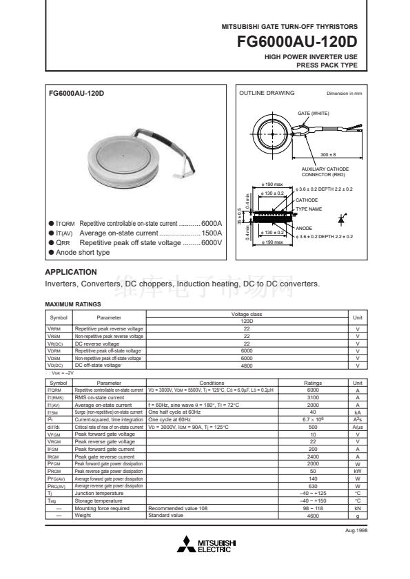
OUTLINE DRAWING
Dimension in mm
GATE (WHITE)
300 鹵 8
AUXILIARY CATHODE
CONNECTOR (RED)
蠁
190 max
0.4 min
蠁
130 鹵 0.2
蠁
3.6 鹵 0.2 DEPTH 2.2 鹵 0.2
CATHODE
TYPE NAME
q
I
TQRM
Repetitive controllable on-state current ...........6000A
q
I
T(AV)
Average on-state current .....................1500A
q
Q
RR
Repetitive peak off state voltage .........6000V
q
Anode short type
35 鹵 0.5
0.4 min
蠁
130 鹵 0.2
蠁
190 max
ANODE
蠁
3.6 鹵 0.2 DEPTH 2.2 鹵 0.2
APPLICATION
Inverters, Converters, DC choppers, Induction heating, DC to DC converters.
MAXIMUM RATINGS
Symbol
V
RRM
V
RSM
V
R(DC)
V
DRM
V
DSM
V
D(DC)
+
: V
GK
= 鈥?V
Parameter
Repetitive peak reverse voltage
Non-repetitive peak reverse voltage
DC reverse voltage
Repetitive peak off-state voltage
+
Non-repetitive peak off-state voltage
+
DC off-state voltage
+
Parameter
Repetitive controllable on-state current
RMS on-state current
Average on-state current
Surge (non-repetitive) on-state current
Current-squared, time integration
Critical rate of rise of on-state current
Peak forward gate voltage
Peak reverse gate voltage
Peak forward gate current
Peak gate reverse current
Peak forward gate power dissipation
Peak reverse gate power dissipation
Average forward gate power dissipation
Average reverse gate power dissipation
Junction temperature
Storage temperature
Mounting force required
Weight
Voltage class
120D
22
22
22
6000
6000
4800
Conditions
V
D
= 3000V, V
DM
= 5500V, T
j
= 125擄C, C
S
= 6.0碌F, L
S
= 0.2碌H
f = 60Hz, sine wave
胃
= 180擄, T
f
= 72擄C
One half cycle at 60Hz
One cycle at 60Hz
V
D
= 3000V, I
GM
= 90A, T
j
= 125擄C
Ratings
6000
3100
2000
40
6.7
脳
10
6
500
10
22
200
2400
2000
50
140
630
鈥?0 ~ +125
鈥?0 ~ +150
98 ~ 118
4600
Unit
V
V
V
V
V
V
Unit
A
A
A
kA
A
2
s
A/碌s
V
V
A
A
W
kW
W
W
擄C
擄C
kN
g
Aug.1998
Symbol
I
TQRM
I
T(RMS)
I
T(AV)
I
TSM
I
2t
d
iT
/d
t
V
FGM
V
RGM
I
FGM
I
RGM
P
FGM
P
RGM
P
FG(AV)
P
RG(AV)
T
j
T
stg
鈥?/div>
鈥?/div>
Recommended value 108
Standard value


 1
1
 2
2
 3
3
 4
4
