MITSUBISHI GATE TURN-OFF THYRISTORS
FG2000JV-90DA
HIGH POWER INVERTER USE
PRESS PACK TYPE
FG2000JV-90DA
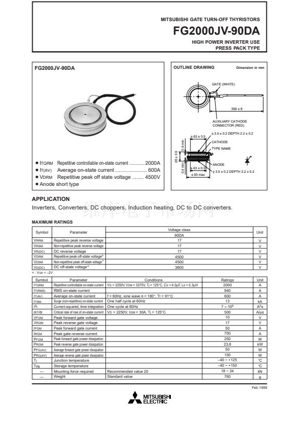
OUTLINE DRAWING
Dimension in mm
GATE (WHITE)
356 鹵 8
AUXILIARY CATHODE
CONNECTOR (RED)
蠁
63 鹵 0.5
0.4 min
蠁
3.5 鹵 0.2 DEPTH 2.2 鹵 0.2
CATHODE
TYPE NAME
隆I
TQRM
Repetitive controllable on-state current ............. 2000A
隆I
T(AV)
Average on-state current ...................... 600A
隆V
DRM
Repetitive peak off state voltage ........ 4500V
隆Anode
short type
26 鹵 0.5
0.4 min
蠁
63 鹵 0.5
蠁
93 max
ANODE
蠁
3.5 鹵 0.2 DEPTH 2.2 鹵 0.2
APPLICATION
Inverters, Converters, DC choppers, Induction heating, DC to DC converters.
MAXIMUM RATINGS
Symbol
V
RRM
V
RSM
V
R(DC)
V
DRM
V
DSM
V
D(DC)
+
: V
GK
= 鈥?V
Parameter
Repetitive peak reverse voltage
Non-repetitive peak reverse voltage
DC reverse voltage
Repetitive peak off-state voltage
+
Non-repetitive peak off-state voltage
+
DC off-state voltage
+
Parameter
Repetitive controllable on-state current
RMS on-state current
Average on-state current
Surge (non-repetitive) on-state current
Current-squared, time integration
Critical rate of rise of on-state current
Peak forward gate voltage
Peak reverse gate voltage
Peak forward gate current
Peak gate reverse current
Peak forward gate power dissipation
Peak reverse gate power dissipation
Average forward gate power dissipation
Average reverse gate power dissipation
Junction temperature
Storage temperature
Mounting force required
Weight
Voltage class
90DA
17
17
17
4500
4500
3600
Conditions
V
D
= 2250V, V
DM
= 3375V, T
j
= 125擄C, C
S
= 4.0碌F, L
S
= 0.3碌H
f = 60Hz, sine wave
胃
= 180擄, T
f
= 91擄C
One half cycle at 60Hz
One cycle at 60Hz
V
D
= 2250V, I
GM
= 30A, T
j
= 125擄C
Ratings
2000
940
600
13
7
脳
10
5
500
10
17
50
700
250
23.8
50
150
鈥?0 ~ +125
鈥?0 ~ +150
18 ~ 24
760
Unit
V
V
V
V
V
V
Unit
A
A
A
kA
A
2
s
A/碌s
V
V
A
A
W
kW
W
W
擄C
擄C
kN
g
Feb.1999
Symbol
I
TQRM
I
T(RMS)
I
T(AV)
I
TSM
I
2t
d
iT
/d
t
V
FGM
V
RGM
I
FGM
I
RGM
P
FGM
P
RGM
P
FG(AV)
P
RG(AV)
T
j
T
stg
鈥?/div>
鈥?/div>
Recommended value 20
Standard value


 1
1
 2
2
 3
3
 4
4
