PRELIMINARY DATA SHEET
ECP100
1.0 WATT POWER AMPLIFIER
Product Features
100 - 2300MHz
31 dBm P1dB
High Linearity: 47 dBm OIP3
High Efficiency: PAE > 45%
12 dB Linear Gain at 1.96GHz
Single 5V Supply
High Reliabilty
Class A or AB operation
Applications
Basestations and Repeaters
CDMA/GSM/TDMA/EDGE
PCS/CDMA2000/IMT2000/UMTS
Multi-carrier systems
Packages Available
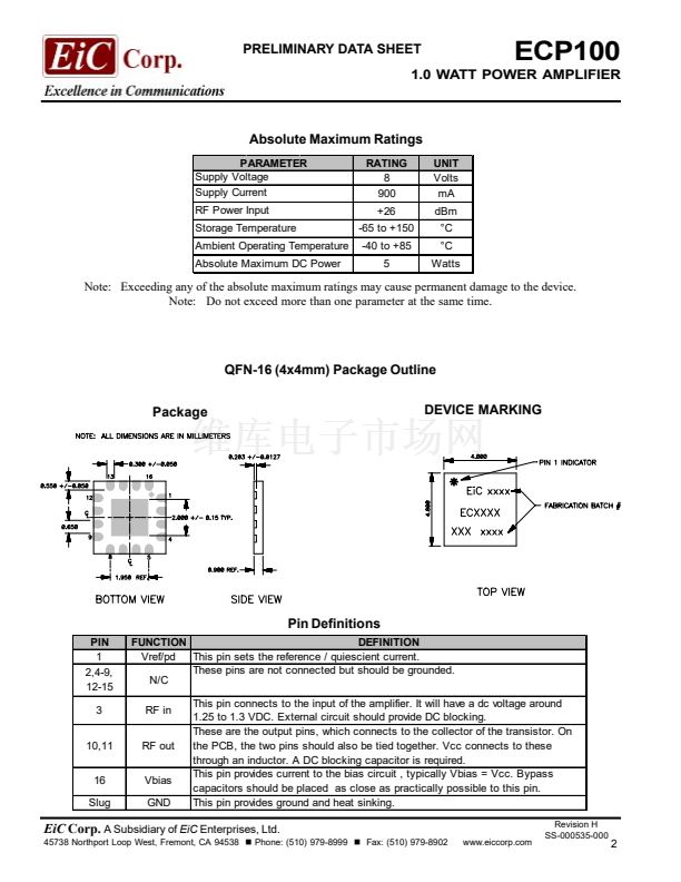
QFN-16 (4x4mm)
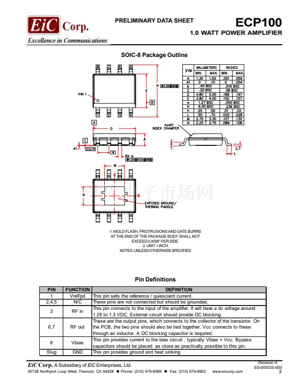
SOIC-8
Product Description
The ECP100 is a single stage, 1.0W power amplifier that offers excellent linearity and efficiency. This device was
developed using EiC鈥檚 proprietary InGaP Heterojunction Bipolar Transistor (HBT) process. The devices have a
partially matched input impedance. It is optimized for multicarrier applications and allows customers to use class A
or class AB operations. The devices can be easily matched in output side to obtain the optimum power, linearity and
efficiency. The product is targeted for use as a driver amplifier for wireless infrastructure applications. It is available in
two surface-mount plastic packages: QFN-16 (4x4mm) and SOIC-8.
Electrical Specifications
o
SYMBOL
F
G
Test Conditions: Ta = 25 C, V
CC
= +5 V Vref = + 5V Icq = 450 mA (class A operation)
PARAMETER
Frequency
Gain (Small Signal)
Output Power @ 1dB
Compression
Output Third Order Intercept
Pout = 25.5dBm (IS-95)
Pout = 23dBm (WCDMA)
Gain Flatness (120MHz Band)
RL
in
I
cop
Vde
c
胃
j
MIN.
100
f = 900MHz
f = 1960MHz
f = 2140MHz
f = 900MHz
f = 1960MHz
f = 2140MHz
f = 900MHz
f = 1960MHz
f = 2140MHz
f = 1960MHz
f = 2140MHz
f = 2140MHz
f = 2140MHz
16.0
11.0
10.0
30.0
30.0
29.5
45.0
45.0
45.0
LIMITS
TYP.
17.0
12.0
11.5
30.5
31.0
31.0
47.0
47.0
46.0
-45
-45
鹵0.5
15.0
540
5.0
30
MAX.
2300
UNIT
MHz
dB
TEST CONDITION
P1dB
dBm
OIP3
ACPR1
ACPR1
dBm
dBc
dBc
dB
dB
mA
Vdc
擄C/W
Note 1
(9 ch. Fwd.)
Note 2
Input Return Loss (50 Ohm)
Operational Current @ P1dB
Device Voltage
Thermal Resistance
Note 3
Note 1: OIP3 = Pout (by power meter, total 2-tone power) + (IM3(dB))/2) - 3dB
Note 2: ACPR measured for 3GPP test model 1, 64 DPCH. Channel bandwidth = 3.84MHz. Frequency offset: +/- 5MHz.
Note 3:
胃
jc is measured between the device junction and the exposed die attach pad.
Note 4: For the recommended mounting solution please refer to APNOTE AP-000556-000.
CAUTION!
SENSITIVE ELECTRONIC DEVICE
EiC
Corp.
A Subsidiary of
EiC
Enterprises, Ltd.
45738 Northport Loop West, Fremont, CA 94538
Phone: (510) 979-8999
Fax: (510) 979-8902
www.eiccorp.com
Revision H
SS-000535-000
1


 1
1
 2
2
 3
3
 4
4
 5
5
 6
6
 7
7
 8
8
 9
9
 10
10
 11
11
 12
12
 13
13
 14
14
 15
15
 16
16
 17
17
