AN1003
Termination Techniques for
ECL / LVECL / PECL / LVPECL Devices
HIGH-PER.ORMANCE PRODUCTS
Different Termination Schemes
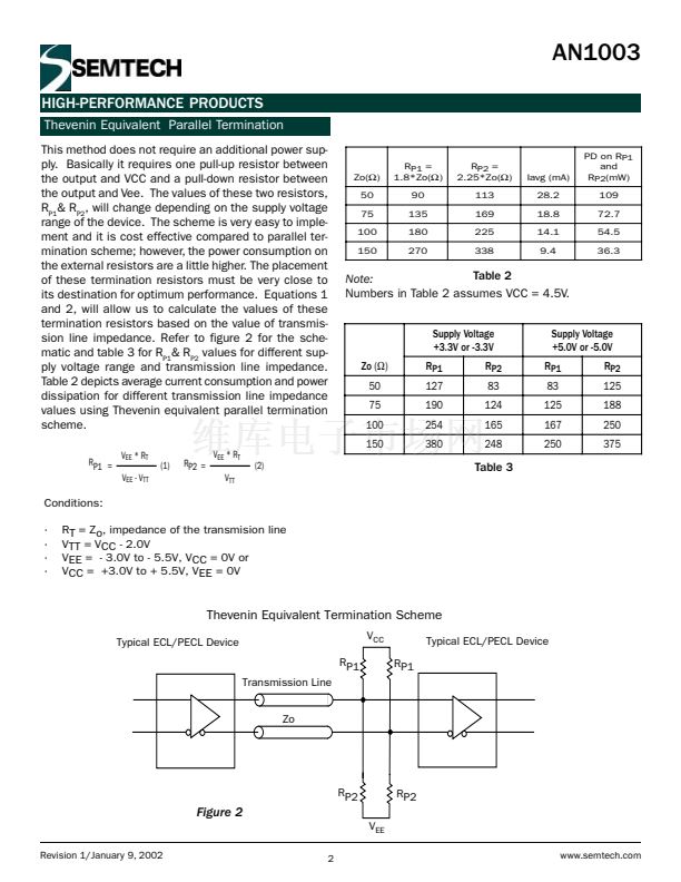
In this application note we will talk about the different
ECL / PECL output termination schemes and AC cou-
pling of the ECL / PECL inputs and outputs.
Any signal path on a printed circuit board may be con-
sidered as a form of transmission line. If the line propa-
gation delay is short with respect to the rise time of
the signal then the reflections are masked out and
are not seen as an overshoot or ringing; thus when
the edge speed increases with faster forms of logic,
the line lengths should be shorter in order to retain
signal integrity.
When high-speed signals are transmitted over long
lines, terminations should be used to minimize reflec-
tions and signal distortion. These reflections cause
ringing on the signal line, which, if severe, will affect
system noise immunity. The reflections appear as over-
shoot and undershoot on the output waveform.
In ECL systems, every output must be terminated
matching the characteristic impedance of the trans-
mission lines. Some of the most popular values of
the transmission line impedance are 50 to 75鈩?for
multilayer etched boards, 100鈩?for multi-wire boards,
and 100 to 120鈩?for wire-wrap boards. Standard pre-
packaged termination resistors are available with val-
ues of 50, 68, 75 and 100鈩?
In this application note, we will discuss four types
terminations mentioned below:
1. Parallel Termination
2. Thevenin equivalent parallel termination
3. Series Termination
4. 鈥淵鈥?Termination
Parallel Termination
In this method, the ECL / PECL outputs are terminated
with a termination resistor, R
P
, to a termination supply
voltage of VTT = Vcc-2.0V. The value of Rp must be
equal to the impedance of the transmission line, Zo.
See Figure 1. If there is a mismatch, line reflections will
be present with an increase in both noise and propaga-
tion delay. The placement of the termination resistors
is important and they should be placed as close to their
destination as possible. In this parallel terminated lines,
the line termination supplies the output pull-down resis-
tors; consequently, no pull-down resistors are required
at the outputs of the driving gate. The advantage of
using this method is that the average power consump-
tion is reduced but on the flip side, it requires an addi-
tional power supply. Average current consumption and
power dissipation may be of interest when using this
termination scheme, Table 1 shows average current and
power dissipation for different transmission lines.
Zo
RP
RP
Figure 1
VCC - 2.0 V
PDavg (mW)
Zo
50
75
100
150
Rp
50
75
100
150
Iavg (mA) IC Output
14
9.3
7.3
5
14
9.5
7.3
4.9
Rp
13
9.1
7.1
5
Table 1
Revision 1/January 9, 2002
1
www.semtech.com


 1
1
 2
2
 3
3
 4
4
 5
5
 6
6
