鈥?鈥?鈥?鈥?/div>
N/C = No Internal Connection
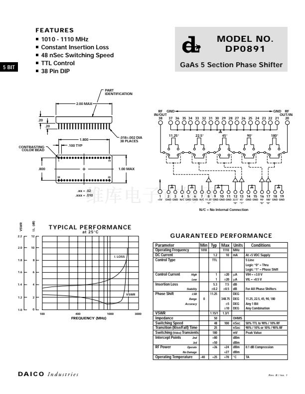
I.L. (dB)
VSWR
TYPICA L P ER F O R MA N CE
at 25
擄C
2.2
12
G U AR ANT EE D PE RF ORM A NCE
Parameter
I. LOSS
2.0
10
Min Typ Max Units
1010
1.2
TTL
1110
10
MHz
mA
Conditions
At +5 VDC Supply
5 Line
Logic 鈥?鈥?= Thru
Logic 鈥?鈥?= Phase Shift
VIH = +3.0 V
VIL = +0.5 V
For All Phase Shifters
11.25, 22.5, 45, 90, 180
Any 1 Bit
Any Combination
1.8
8
Operating Frequency
DC Current
Control Type
1.6
6
Control Current
Insertion Loss
High
Low
1.4
4
VSWR
2
Stability
Phase Shift
LSB
Range
Accuracy
1
1
5.3
鹵0.2
11.25
0
1.2
1.0
0
100
400
1000
3000
FREQUENCY (MHz)
VSWR
Impedance
Switching Speed
Transition (Rise/Fall) Time
Switching
(Video)
Transients
Intercept Points
2nd
3rd
RF Power
Operate
No Damage
Operating Temperature
-40
碌A(chǔ)
碌A(chǔ)
dB
dB
DEG
348.75 DEG
鹵5
DEG
鹵10
DEG
1.15/1 1.3/1
50
OHMS
48
100 nSec
25
nSec
180
mV
+80
dBm
+50
dBm
+26
+24 dBm
+27 dBm
+25
+70
擄C
鹵20
鹵20
7.5
鹵0.5
50% TTL to 90% / 10% RF
90% / 10% or 10% / 90% RF
Peak Value
0.1 dB Compression
TA
DA I C O
In d u s t r i e s
Rev. B / Iss. 1


 1
1
