DM74LS533 Octal Transparent Latch with 3-STATE Outputs
October 1988
Revised March 2000
DM74LS533
Octal Transparent Latch with 3-STATE Outputs
General Description
The DM74LS533 consists of eight latches with 3-STATE
outputs for bus organized system applications. The flip-
flops appear transparent to the data when Latch Enable
(LE) is HIGH. When LE is LOW, the data that meets the
setup times is latched. Data appears on the bus when the
Output Enable (OE) is LOW. When OE is HIGH the bus
output is in the high impedance state. The DM74LS533 is
the same as the DM74LS373, except that the outputs are
inverted. For detailed specifications please see the
DM74LS373 data sheet, but note that the propagation
delays from data to output are 5.0 ns longer for the
DM74LS533 than for the DM74LS373.
Features
s
Eight latches in a single package
s
3-STATE outputs for bus interfacing
Ordering Code:
Order Number
DM74LS533WM
DM74LS533N
Package Number
M20B
N20A
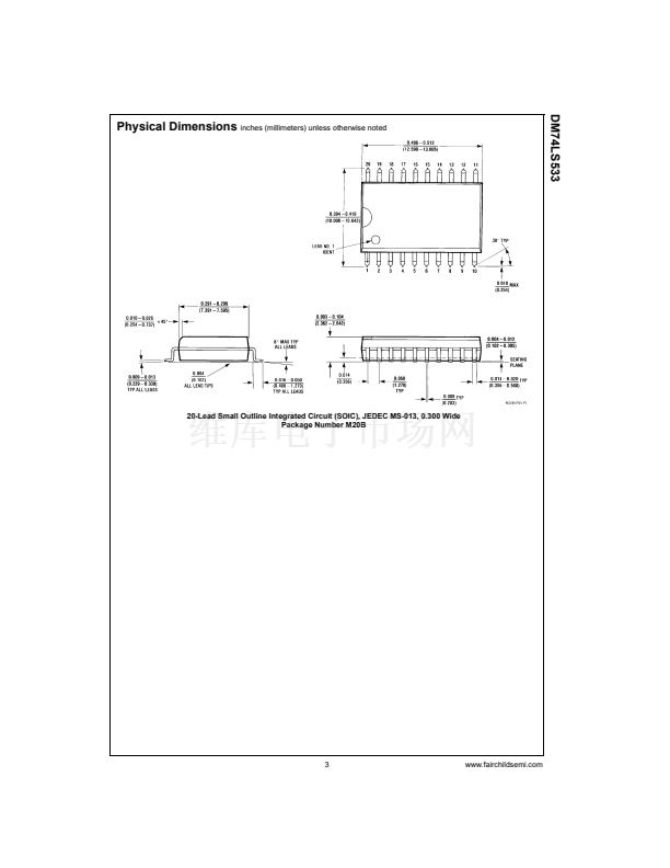
Package Description
20-Lead Small Outline Integrated Circuit (SOIC), JEDEC MS-013, 0.300 Wide
20-Lead Plastic Dual-In-Line Package (PDIP), JEDEC MS-001, 0.300 Wide
Devices also available in Tape and Reel. Specify by appending the suffix letter 鈥淴鈥?to the ordering code.
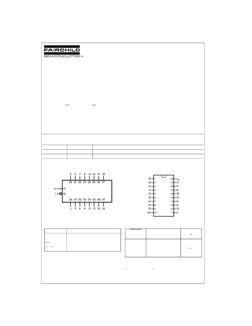
Logic Symbol
Connection Diagram
V
CC
=
Pin 20
GND
=
Pin 10
Pin Descriptions
Pin Names
D0, D7
LE
OE
O0鈥揙7
Data Inputs
Latch Enable Input (Active HIGH)
Output Enable Input (Active LOW)
Complementary 3-STATE Outputs
Description
Function Table
OUTPUT
Enable
L
L
L
H
L
=
LOW State
H
=
HIGH State
X
=
Don't Care
Z
=
High Impedance State
Q
O
=
Previous Condition of O
Latch
Enable
H
H
L
X
D
H
L
X
X
Output
O
L
H
Q
O
Z
漏 2000 Fairchild Semiconductor Corporation
DS009811
www.fairchildsemi.com


 1
1
 2
2
 3
3
 4
4
