DM74LS279 Quad S-R Latch
August 1986
Revised March 2000
DM74LS279
Quad S-R Latch
General Description
The DM74LS279 consists of four individual and indepen-
dent Set-Reset Latches with active low inputs. Two of the
four latches have an additional S input ANDed with the pri-
mary S input. A LOW on any S input while the R input is
HIGH will be stored in the latch and appear on the corre-
sponding Q output as a HIGH. A LOW on the R input while
the S input is HIGH will clear the Q output to a LOW. Simul-
taneous transition of the R and S inputs from LOW-to-
HIGH will cause the Q output to be indeterminate. Both
inputs are voltage level triggered and are not affected by
transition time of the input data.
Ordering Code:
Order Number
DM74LS279M
DM74LS279N
Package Number
M16A
N16E
Package Description
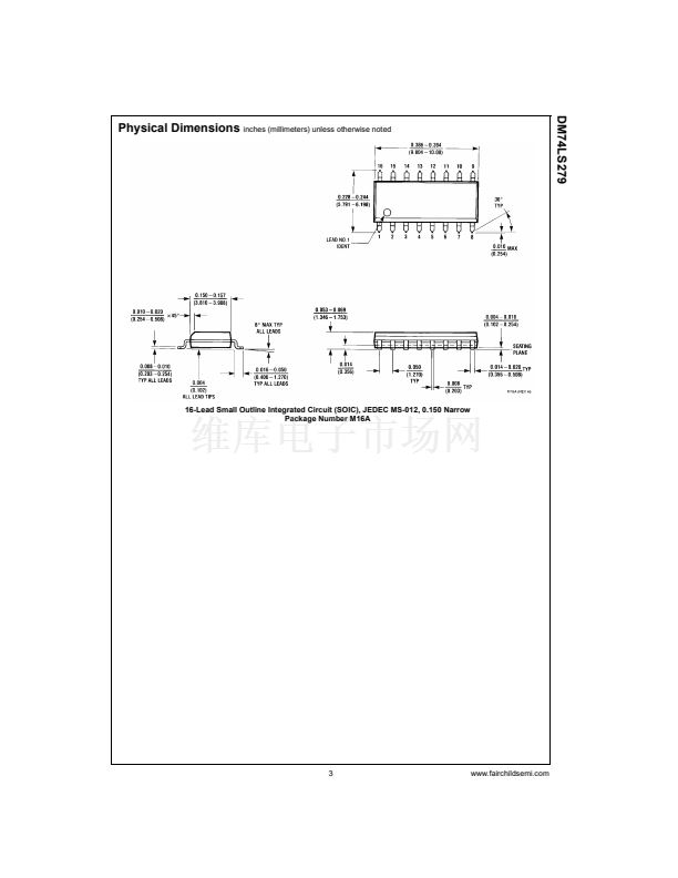
16-Lead Small Outline Integrated Circuit (SOIC), JEDEC MS-012, 0.150 Narrow
16-Lead Plastic Dual-In-Line Package (PDIP), JEDEC MS-001, 0.300 Wide
Devices also available in Tape and Reel. Specify by appending the suffix letter 鈥淴鈥?to the ordering code.
Connection Diagram
Function Table
Inputs
S (Note 1)
L
L
H
H
R
L
H
L
H
Output
Q
H (Note 2)
H
L
Q
0
H
=
HIGH Level
L
=
LOW Level
Q
0
=
The Level of Q before the indicated input conditions were established.
Note 1:
For latches with double S inputs:
H
=
both S inputs HIGH
L
=
one or both S inputs LOW
Note 2:
This output level is pseudo stable; that is, it may not persist when
the S and R inputs return to their inactive (HIGH) level.
漏 2000 Fairchild Semiconductor Corporation
DS006420
www.fairchildsemi.com


 1
1
 2
2
 3
3
 4
4
