鈥?/div>
2.5V or 3.3V operation
Split output bank power supplies
Output frequency range: 6 MHz to 200 MHz
Output-output skew < 150 ps
Cycle-cycle jitter < 100 ps
Selectable positive or negative edge synchronization
Selectable phase-locked loop (PLL) frequency range
8 LVTTL outputs driving 50鈩?terminated lines
LVCMOS/LVTTL Over-voltage tolerant reference input
2x, 4x multiply and (1/2)x, (1/4)x divide ratios
Spread-Spectrum-compatible
Pin-compatible with IDT5V9950 and IDT5T9950
Industrial temperature range: 鈥?0擄C to +85擄C
32-pin TQFP package
Description
The CY2V9950 is a low-voltage, low-power, eight-output,
200-MHz clock driver. It features functions necessary to
optimize the timing of high performance computer and
communication systems.
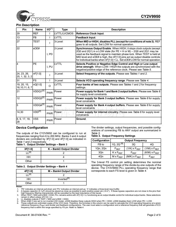
The user can program the output banks through 3F[0:1] and
4F[0:1]pins. Any one of the outputs can be connected to
feedback input to achieve different reference frequency multi-
plication and divide ratios and zero input-output delay.
The device also features split output bank power supplies
which enable the user to run two banks (1Qn and 2Qn) at a
power supply level different from that of the other two banks
(3Qn and 4Qn). Additionally, the PE pin controls the synchro-
nization of the output signals to either the rising or the falling
edge of the reference clock.
Block Diagram
Pin Configuration
TES T
PE
FS VDDQ 1
TEST
VDD
REF
2F1
3F0
REF
3
3
PLL
FB
32 31 30 29 28 27 26 25
3F1
4F0
4F1
PE
VDDQ4
2Q0
1
2
3
4
5
6
7
8
9 10 11 12 13 14 15 16
VDDQ3
VSS
FS
2F0
24
23
22
1F1
1F0
sOE#
VDDQ1
1Q0
1Q1
VSS
VSS
21
20
19
18
17
1Q0
1F1:0
1Q1
CY2V9950
4Q1
4Q0
VSS
2F1:0
2Q1
3
3Q0
3Q1
V DDQ3
3Q1
3
3
4Q0
/M
4F1:0
3
4Q1
V DDQ4 sOE #
Cypress Semiconductor Corporation
Document #: 38-07436 Rev. **
鈥?/div>
3901 North First Street
鈥?/div>
San Jose
,
CA 95134
鈥?/div>
408-943-2600
Revised January 9, 2003
VSS
/K
VDD
3Q0
FB
3F1:0
2Q1
2Q0


 1
1
 2
2
 3
3
 4
4
 5
5
 6
6
 7
7
 8
8
 9
9
